
Circuit Diagram
Index 905
VIDEO_SIGNAL_CLAMP
Published:2009/7/9 2:59:00 Author:May
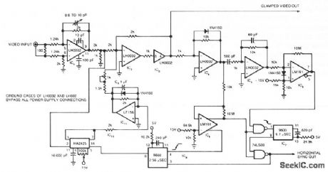
The circuit uses a track-and-hold amplifier in a closed-loop configuration to clamp the back-porch voltage of a standard video waveform to O V. The circuit's outputs include a clamped composite-video signal and a TTL-level horizontal-blanking pulse. Differential input buffer IC1 and the summing amplifier IC2 isolate the input video signal. Clipper IC4 removes the video signal, leaving only the synchronization information. Differentiator IC5 detects the edges of the horizontal blanking pulses and produces pulses that correspond to the leading and trailing edges of the horizontal blanking pulses. IC6 clips these pulses and converts them to a TTL level. IC7 uses these clipped pulses to generate a TTL-level window that, when combined with the horizontal pulse generated by IC8, forms a TTL representation of the original horizontal pulse. This representation is synchronized to the input waveform. IC9 uses the trailing edge of this reconstructed waveform to generate the track pulse for track-and-hold amplifier IC10. IC11 filters 1010's dc output and, after gain adjustment, feeds it back to IC2's summing node. (View)
View full Circuit Diagram | Comments | Reading(1560)
SIMPLE_POWER_SUPPLY
Published:2009/7/9 2:59:00 Author:May
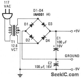
This power supply delivers plus and minus 9 V to replace two 9-V batteries. The rectifier circuit is actually two separate full-wave rectifters fed from the secondary of the transformer. One full-wave rectifier is composed of diodes D1 and D2, which develop + 9 V, and the other is composed of D3 and D4, which develop -9 V.Each diode from every pair rectifies 6.3 Vac, half the secondary voltage, and charges the associ-ated filter capacitor to the peak value of the ac waveform, 6.3 x 1.414 = 8.9 V. Eachdiode should have a PIV, Peak Inverse Voltage, rating that is at least twice the peak voltage from the transformer, 2 x 8.9 = 18 V. The 1N4001 has a PIV of 50 V. (View)
View full Circuit Diagram | Comments | Reading(1307)
SIMPLE_40_dB_GAIN_AMPLIFIER
Published:2009/7/9 2:58:00 Author:May
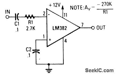
An LM382 low-noise preamp is used here to obtain a 40-dB gain amplifier, using only the IC and three peripheral components. (View)
View full Circuit Diagram | Comments | Reading(872)
FLOOD_ALARM
Published:2009/7/9 2:57:00 Author:May
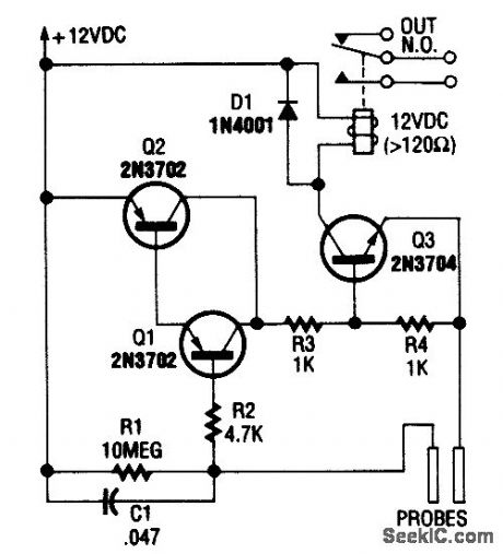


Using a few bipolar transistors, this circuit acts as a flood alarm. When liquid touches the probes,leakage current biases Q1, Q2, and Q3 (a dc-cou pled amplifier) into conduction, which activates the relay. The contacts can be hooked into the alarm system. (View)
View full Circuit Diagram | Comments | Reading(0)
LOW_NOISE_PHONO_PREAMP
Published:2009/7/9 2:57:00 Author:May

This circuit uses an LM381/1A as a low-noise phono preamp. The feedback network provides RIAA compensation. (View)
View full Circuit Diagram | Comments | Reading(2633)
12_VOC_BATTERY_OPERATED_120_VAC_POWER_SOURCE
Published:2009/7/9 2:56:00 Author:May
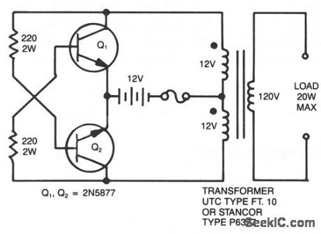


A simple 120 V: 24 V, center-tapped control transformer and four additional components can do the job. This circuit outputs a clean 200 V pk-pk square wave at 60 Hz and can supply up to 20 W. The circuit is self-starting and free-running.If Q1 is faster and has a higher gain than Q2, it will turn on first when you apply the input power and will hold Q2 off. Load current and transformer magnetizing current then flows in the upper half of the primary winding, and auto transformer action supplies the base drive until the transformer saturates. When that action occurs, Q1 loses its base drive. As it turns off, the transformer voltages reverse, turning Q2 on and repeating the cycle. The output frequency depends on the transformer iron and input voltage, but not on the load. The frequency will generally range between 50 to 60 Hz with a 60-Hz transformer and car battery or equivalent source. The output voltage depends on turns ratio and the difference between input voltage and transistor saturation voltage. For higher power, use larger transformers and transistors. This type of inverter normally is used in radios, phonographs, hand tools, shavers, and small fluorescent lamps. It will not work with reactive loads (motors) or loads with high inrush currents, such as coffee pots, frying pans, and heaters. (View)
View full Circuit Diagram | Comments | Reading(1932)
SIMPLE_TAPE_PLAYBACT_AMPLIFIER
Published:2009/7/9 2:56:00 Author:May
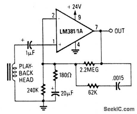
This circuit uses an LM381/1A as a tape pre-amp. The feedback network includes NAB Equali-zation. (View)
View full Circuit Diagram | Comments | Reading(947)
MOISTURE_DETECTOR
Published:2009/7/9 2:54:00 Author:May

A bar-graph LED driver is used to drive 10 LEDs to give a relative indication of moisture. The mois-ture probes are connected so that electrical conductivity due to moisture tends to forward bias Q1, provid-ing a dc voltage at pin 5 of U1 that is proportional to leakage current. Ideally, the probes should be made of stainless steel. (View)
View full Circuit Diagram | Comments | Reading(0)
GENERAL_PURPOSE_VIDEO_SWITCH
Published:2009/7/9 2:54:00 Author:May

The circuit shown provides 40-dB isolation at 6 MHz and is good for general purpose video switching. (View)
View full Circuit Diagram | Comments | Reading(0)
COLOR_TV_CROSSHATCH_GENERATOR
Published:2009/7/9 2:53:00 Author:May

This circuit provides a simple, low-cost crosshatch generator tor convergence and geometry adjustments on color TVs. The generator is driven by two clocks, one for the horizontal drive, IC1ab, and one for the vertical drive, IC2ab. The clock outputs are applied to the two binary counters contained in IC5 which generate the line and field sync pulses and respective blanking periods. Line clock pulses, buffered by IClc, are differentiated by C3/R5 to produce the vertical bars. These bars are gated by IC4a which suppresses the bars during the line blanking period produced by the coincidence of Q3, Q4 outputs of IC5a, detected by IC4b. This output is also differentiated by C5/R7 to produce the line sync pulse, LS. A similar process is used to generate horizontal lines and the field sync, except that in order to give the correct aspect ratio, the count of IC5b is reset at 12, coincidence of Q3 and Q4. In coincidence of Q2, Q4 is used to generate the sync pulse FS and the blanking period. The line and field sync pulses, LS and FS, are combined in IC4d. (View)
View full Circuit Diagram | Comments | Reading(1580)
ELECTRONIC_LEVEL
Published:2009/7/9 2:52:00 Author:May


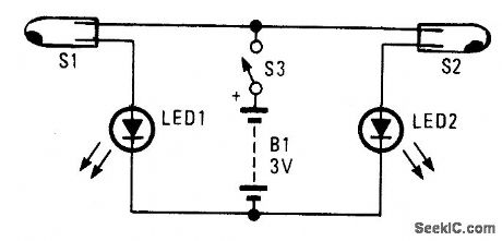
An electronic level can be constructed using two mercury switches mounted on an absolutely flatboard,along with the LEDs.If one LED lights,the surfaceis not level,If both light,the surface is level. (View)
View full Circuit Diagram | Comments | Reading(943)
FULL_BATHTUB_INDICATOR
Published:2009/7/9 2:52:00 Author:May
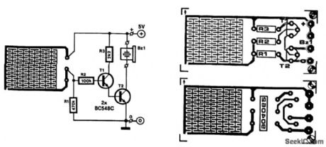
Running a bath can end in a minor domestic disaster if you forget to turn off the taps 'n time. This indicator activates an active buzzer to provide an audible warning when a given water level is reached.
Because the water sensor and the driver circuit for the buzzer are contained on one PC board, the indicator, together with the 9-V battery and the buzzer, can be built into a compact case. Obviously, the sensor, which is etched on the PC-board, must not be fitted in case-iron or steel bath, the indicator is secured to it with the aid of a magnet glued onto the case. To prevent scratching the bath, the magnet can be covered in plastic or rubber. If you have a polypropylene bath, the indicator can be stuck to it with blue tack or double-sided adhesive tape.
When the water reaches the sensor, the base of T1 is connected to the positive supply line. As a result, T1 and T2 are switched on so that the buzzer BZ1, a self-oscillating type, is activated. The current drawn by the circuit in that condition is about 25 mA.
In case the circuit is actuated by steam, its sensitivity can be reduced by increasing the value of R2. It is best to tin the PC board tracks to prevent corrosion.
T1, T2=BC548CBZ1 = active piezo-ceramic resonator (View)
View full Circuit Diagram | Comments | Reading(1920)
The auto control circuit of the stone pile hammer
Published:2011/7/22 6:37:00 Author:qqtang | Keyword: auto control circuit, pile hammer
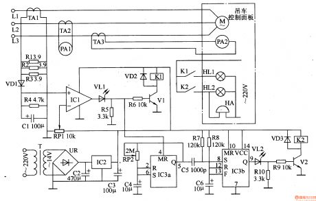
The working principle of the circuit The auto control circuit of the stone pile hammer consists of the power supply circuit, current detection and indicating circuit and the control alarm circuit, see as figure 8-141.
The power supply circuit consists of the transformer T, rectifier bridge pile UR, filter capacitors C2 and C3 and the 3-phase regulated integrated circuit IC2. The current detection and indicating circuit consists of the mutual inductor TAl-TA3, resistor R1-R4, potentiometer RP1, diode VD1, capacitor C1, ampere meters of PA1 of PA2 and computer integrated circuit IC1. (View)
View full Circuit Diagram | Comments | Reading(638)
EEG_WAVEFORM_ANALYZER
Published:2009/7/20 20:40:00 Author:Jessie
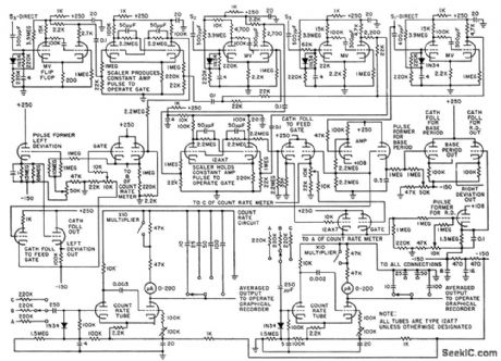
Uses derivative curves of primary eeg signals to quantitatively describe waveshape deviations of irregular electrical waveforms emitted by brain, in terms of time and amplitude. Oporates on zero-crossing detector measurements to produce analog voltages proportional to time between base periods and also proportional to time values of left and right deviation coefficients.-C. J. Zaander, Computer Ancalyzes Brain Waveforms, Electronics, 31:29, p 68-72. (View)
View full Circuit Diagram | Comments | Reading(0)
TWO_STAGE_SOLID_STATE_VIDEO_AMPLIFIER
Published:2009/7/20 20:39:00 Author:Jessie

Provides cathode drive for crt of tv receiver, along with sync takeoff from driver. Driver also serves as sync amplifier, first sound amplifier, and keyer for agc stage. -D, L, Wollensen, Solid-State Television Video Amplifiers, Motorola Application Note AN-165, Doc. 1965.
(View)
View full Circuit Diagram | Comments | Reading(605)
HORIZONTAL_SYNC_TRANSIENT_DISPLAY
Published:2009/7/20 20:38:00 Author:Jessie

Reed switch operated at field frequency from ac heater voltage, with permanent magnet providing magnetic bias to get 60 cps, permits observing single transient continuously while making tv receiver circuit adjustment. -M. B. Knight, Reed Switches for Breadboarding, Electronics, 37:16, p 93 (View)
View full Circuit Diagram | Comments | Reading(589)
The plastic regenerator control circuit
Published:2011/7/21 22:21:00 Author:qqtang | Keyword: plastic regenerator, control circuit

The working principle of the circuit The plastic regenerator control circuit consists of the motor main control circuit and electric heater temperature control circuit, see as figure 8-140.
The motor main control circuit consists of edge switch Q, fuses of FU1 and FU2, the AC contactor KMI, heat relay KR, stop key SI, starting key S2 and motor M. The heater temperature control circuit consists of the AC contactors of KM1 and KM2, the temperature controllers A and B, the plastic pre-heater EHI and melting heater EH2. (View)
View full Circuit Diagram | Comments | Reading(591)
NERVE_STIMULATOR
Published:2009/7/20 20:38:00 Author:Jessie
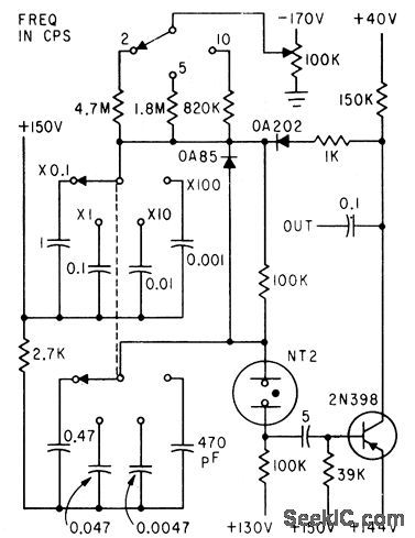
Neon relaxation oscillator and transistor give stable pulse gen erator covering range of 0.2 to 2,500 cps for neurophysiology research.-R. D. Ryan, Low-Cost Pulse Generator, Electronics, 35:15, p 70. (View)
View full Circuit Diagram | Comments | Reading(1378)
HORIZONTAL_DEFLECTION
Published:2009/7/20 20:38:00 Author:Jessie
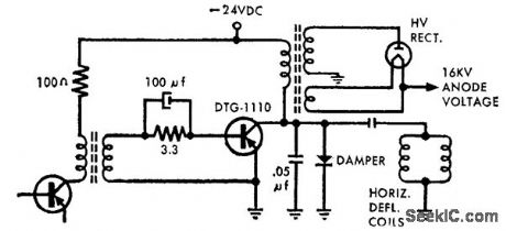
Uses 200-v 15-amp transistor with high power dissipation characteristics and low thermal resistance. Drive requirements are substantially reduced because transistor has high saturated current gain.-High-Power Nu-Base Germanium Transistors (Delco Radio ad), Electronics, 39:7, p 20-21. (View)
View full Circuit Diagram | Comments | Reading(961)
BLOOD_PRESSURE_INDICATOR
Published:2009/7/20 20:37:00 Author:Jessie
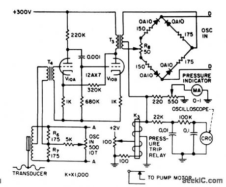
Transducer bridge is energized at points A-A by external 3-kc oscillator. Unbalance voltage is amplified by V10 and demodulated by second bridge that operates as rectifier with phase discrimination, while energized at D-D by separate 3-kc oscillator source. During unbalance, the only components reaching ring demodulator are those in phase or l80° out of phase with reference carrier voltage, giving positive or negative swing on meter-R.Schild and N. Wesson, Servo Circuit Controls Artificial Heart, Electronics, 31:15, p 73-75. (View)
View full Circuit Diagram | Comments | Reading(1011)
| Pages:905/2234 At 20901902903904905906907908909910911912913914915916917918919920Under 20 |
Circuit Categories
power supply circuit
Amplifier Circuit
Basic Circuit
LED and Light Circuit
Sensor Circuit
Signal Processing
Electrical Equipment Circuit
Control Circuit
Remote Control Circuit
A/D-D/A Converter Circuit
Audio Circuit
Measuring and Test Circuit
Communication Circuit
Computer-Related Circuit
555 Circuit
Automotive Circuit
Repairing Circuit