
Circuit Diagram
Index 916
Voltage_controlled_oscillator_for_FM_operation_using_a_2N4416
Published:2009/7/20 23:37:00 Author:Jessie

Voltage-controlled oscillator for FM operation using a 2N4416 (courtesy Texas Instruments Incorporated). (View)
View full Circuit Diagram | Comments | Reading(1039)
CASCADE_ANGLE_MODULATOR
Published:2009/7/20 23:36:00 Author:Jessie

Gives lwice the modulation index for a particular signal, or 50' for the two sections.-A. C. Todd, P.Schuck, and H. M. Sachs, Using Voltcrge-Var-iable Capodtors in Modukttor Design, Elec-tronics, 34;3, p 56-59. (View)
View full Circuit Diagram | Comments | Reading(534)
HIGH_FREQUENCY_OSCILLATOR
Published:2009/7/9 1:35:00 Author:May

Intended primarily as a building block for a QRP transmitter, this 20-MHz oscillator delivered a clean 6-V, pk-pk signal into a 100-Ω load.
(View)
View full Circuit Diagram | Comments | Reading(721)
Stabilized_Wien_bridge_oscillator
Published:2009/7/20 23:36:00 Author:Jessie

Stabilized Wien bridge oscillator (courtesy Analog Devices, Inc.). (View)
View full Circuit Diagram | Comments | Reading(0)
Current three-phase motor phase-failure protection circuit diagram
Published:2011/8/2 2:39:00 Author:Rebekka | Keyword: Current three-phase motor, phase-failure protection
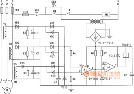
The production of transformer Tl ~ T3 can use the ring ferrite core which is easy to be purchased on the market. It uses Φ0.25mm high-strength wire wound with 150 to 250 turns. The number of the turns is determined by the motor power. If the motor power is low, you can wound more turns. The power supply line passes the ring. The capacitors C1 ~ C3 use the 10μF/25V electrolytic capacitors. C4 uses 0.1μF/63V ceramic chip capacitor; C6 uses 470μF/25V electrolytic capacitor; C5 is the interference absorption capacitor, when the action is too sensitive, it can increase the capacitance value of C5, conversely it will reduce the value of C5, its range is 4.7 ~ 33μF/25V. Resistors Rl = R2 = l.2kΩ, R4 = 390kΩ, R5 = 680kΩ, R6 = 15kΩ, R7 = 2kΩ, the nominal power resistor is 1/8W RJ. Zener VD11's regulator value is about 8V. Other diodes use 1N4004. (View)
View full Circuit Diagram | Comments | Reading(3914)
DELTA_SIGMA_MODULATION_FOR_DIGITALCOMMUNICATIONS
Published:2009/7/20 23:35:00 Author:Jessie

Flip-flop sampling pulse generator supplies 5-mlcrosec pulses at 3-kcprr to modulator that also has analog signal input. Integrated difference signal fires Schmitt trigger to provide positive output that opens gate, passing square-wave pulse that sets flip-flop. Output of flip-flop is fed to emitter-follower and demodulated by ac five low-pass liter having 50-cps cutoff.-H. Inose et al, New Modulation Technique Simplifies Circuits, Electronics, 36:4, p 52-55. (View)
View full Circuit Diagram | Comments | Reading(1030)
75_Ω_VIDEO_PULSE_AMPLIFIER
Published:2009/7/9 1:35:00 Author:May


HA-5190 can drive the 75-Ω coaxial cable with signals up to 2.5 V pk-pk without the need for cur-rent boosting. In this circuit, the overall gain is approximately unity because of the impedance matching network. (View)
View full Circuit Diagram | Comments | Reading(572)
SLIDE_SHOW_TIMER
Published:2009/7/9 1:34:00 Author:May
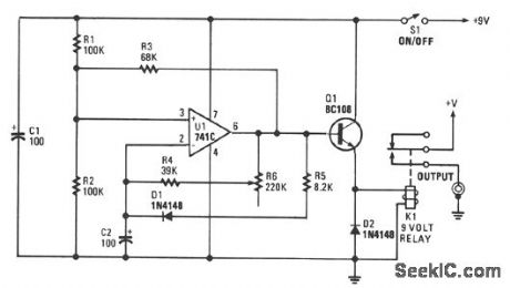
You can set the interval from about 5-30 seconds. A relay operates the slide-change mechanism. Op amp U1 forms a sort of Schmitt trigger. Resistors R1 and R2 bias the noninverting input at pin 3 of U1 to half the supply voltage. Feedback resistor R3 increases or reduces the bias to pin 3, depending on whether the output of U1 is high or low.When power is first applied to the circuit, C2 has a zero charge and the inverting input of the op amp is at a lower voltage than its noninverting input. When the output of U1 is high, C2 begins to charge through R5 and D1. It takes about one second for the charge on C2 to reach the same voltage as that at the noninverting input of U1. At that time, the output of U1 begins a negative swing.Because of the positive feedback through R3, the voltage at the noninverting input is reduced and the output becomes more negative. The voltage at the noninverting input is about 1/4 of the supply voltage, and C2 begins to discharge through the resistor bank. The timing is controlled by R6.The resulting pulses are fed to the base of Q1, configured as an emitter-following buffer stage, which is used to activate relay K1. Transistor Q1 is necessary because op amps usually have an output current in the 20-mA range, which is too low to activate the relay. (View)
View full Circuit Diagram | Comments | Reading(1185)
First_and_second_mixer_stages_for_a_27_MHz_CB_receiver
Published:2009/7/20 23:34:00 Author:Jessie
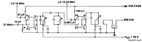
First and second mixer stages for a 27 MHz CB receiver. Note that these two stages replace three in conventional receivers not employing dual-gate MOSFETs (courtesy Texas Instruments Incorporated). (View)
View full Circuit Diagram | Comments | Reading(594)
Overtone_crystal_oscillator_with_operating_range_of_20_MHz_to_100_MHz_depending_on_crystal_selection_and_tank_tuning
Published:2009/7/20 23:32:00 Author:Jessie

Overtone crystal oscillator with operating range of 20 MHz to 100 MHz depending on crystal selection and tank tuning. VEE is -5.2 volts (courtesy Motorola Semiconductor Products Inc.). (View)
View full Circuit Diagram | Comments | Reading(669)
250_KW_PEAK_FROM_SCR
Published:2009/7/20 23:32:00 Author:Jessie
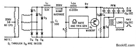
Line-type modulator uses silicon diodes for high-voltage rectifiers, backswing, holdoff, and inverse-diode circuits. Trigger generator uses two-layer and four-layer diodes to provide pulse burst repetition rates up to 25 kc.-H. G. Heard, Controlled Rectifier Produces Quarter-Mega watt Pulse Power, Electronics, 34:25, p 54-55. (View)
View full Circuit Diagram | Comments | Reading(648)
FOUR_RANGE_VTVM
Published:2009/7/20 23:31:00 Author:Jessie

Measures r-f power oscillator output, for establishing irradiation and calibration procedures and positioning techniques when using focused ultrasound for therapeutic treatment of deep-seated brain structures.-B. J. Cosman and T. F.Hueler, Instrumentation for Ultrasonic Neurosurgery, Electronics, 32:20, p 53-57. (View)
View full Circuit Diagram | Comments | Reading(896)
900_MHz_to_45_MHz_mixer_using_a_3N225_dual_gate_MOSFET
Published:2009/7/20 23:31:00 Author:Jessie

900 MHz to 45 MHz mixer using a 3N225 dual-gate MOSFET (courtesy Texas Instruments Incorporated). (View)
View full Circuit Diagram | Comments | Reading(663)
450_432_MHz_PF_amplifier_using_a_3N204_dual_gate_MOSFET
Published:2009/7/20 23:30:00 Author:Jessie

450/432 MHz PF amplifier using a 3N204 dual-gate MOSFET(courtesy TexasInstruments Incorporated). (View)
View full Circuit Diagram | Comments | Reading(1009)
Multicrystal_RF_oscillator_for_the_20_MHz_to_20_MHz_range
Published:2009/7/20 23:30:00 Author:Jessie

Multicrystal RF oscillator for the 2.0 MHz to 20 MHz range (courtesy Motorola Semiconductor Products Inc.). (View)
View full Circuit Diagram | Comments | Reading(814)
BATTERYLESS_CARDIAC_PACEMAKER
Published:2009/7/20 23:30:00 Author:Jessie

Body fluids are electrolyte for implanted silver and zinc electrodes that provide d-c power for four-transistor pacemaker. Secondary of T1 provides feedback for ringing-choke oscillator Q1, which charges C until Q2 is cut off. C then discharges until Q1 can again con duct.-O. Z. Roy and R. W. Wehnert, Keeping the Heart Alive with a Biological Battery, Electronics, 39:6, p 105-107. (View)
View full Circuit Diagram | Comments | Reading(2587)
3_MC_COLPITTS_FOR_TONOMETER
Published:2009/7/20 23:29:00 Author:Jessie


Frequency shift is proportional to pressure on quartz crystal-D. E. Newell, C. H. Horn, and M. L. Rubin, Measuring Eyeball Pressure with a Crystal Oscillator, Electronics, 34:36, p 64-65. (View)
View full Circuit Diagram | Comments | Reading(804)
Fundamental_crystal_oscillator_for_1_MHz_to_20_MHz
Published:2009/7/20 23:28:00 Author:Jessie

Fundamental crystal oscillator for 1 MHz to 20 MHz. VEE is -5.2 volts (courtesy Motorola Semiconductor Products Inc.). (View)
View full Circuit Diagram | Comments | Reading(646)
PILL_TRACING_INTEGRATOR
Published:2009/7/20 23:28:00 Author:Jessie

Voltage proportional to speed of travel of pill-sized radio transmitter in human body is integrated in quantizing circuit that delivers number of pulses proportional to track length. Transistor differential amplifier charges C, and Schmitt trigger controls discharge of C through R2.Frequency of trigger pulses is proportional to input voltage within 1% over range of 2 to 200 mv,-B. Jacobson and B Lindberg, Servo Tracks Pill in Human Body,Electronics,36:12,p58-60. (View)
View full Circuit Diagram | Comments | Reading(1027)
Voltage_controlled_oscillator_using_an_MC1648
Published:2009/7/20 23:18:00 Author:Jessie

Voltage-controlled oscillator using an MC1648. This VCO is tunable from 110 MHz to 145 MHz. The control voltage range is 1.8 volts at 110 MHz to 5 volts at 145 MHz (courtesy Motorola Semiconductor products Inc.). (View)
View full Circuit Diagram | Comments | Reading(4195)
| Pages:916/2234 At 20901902903904905906907908909910911912913914915916917918919920Under 20 |
Circuit Categories
power supply circuit
Amplifier Circuit
Basic Circuit
LED and Light Circuit
Sensor Circuit
Signal Processing
Electrical Equipment Circuit
Control Circuit
Remote Control Circuit
A/D-D/A Converter Circuit
Audio Circuit
Measuring and Test Circuit
Communication Circuit
Computer-Related Circuit
555 Circuit
Automotive Circuit
Repairing Circuit