555 Circuit
SLIDE_SHOW_TIMER
Published:2009/7/9 1:34:00 Author:May | From:SeekIC

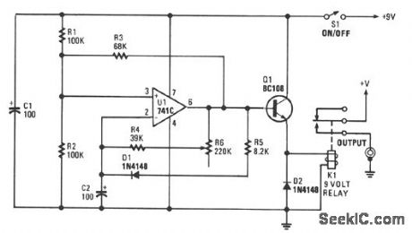
You can set the interval from about 5-30 seconds. A relay operates the slide-change mechanism. Op amp U1 forms a sort of Schmitt trigger. Resistors R1 and R2 bias the noninverting input at pin 3 of U1 to half the supply voltage. Feedback resistor R3 increases or reduces the bias to pin 3, depending on whether the output of U1 is high or low.When power is first applied to the circuit, C2 has a zero charge and the inverting input of the op amp is at a lower voltage than its noninverting input. When the output of U1 is high, C2 begins to charge through R5 and D1. It takes about one second for the charge on C2 to reach the same voltage as that at the noninverting input of U1. At that time, the output of U1 begins a negative swing.Because of the positive feedback through R3, the voltage at the noninverting input is reduced and the output becomes more negative. The voltage at the noninverting input is about 1/4 of the supply voltage, and C2 begins to discharge through the resistor bank. The timing is controlled by R6.The resulting pulses are fed to the base of Q1, configured as an emitter-following buffer stage, which is used to activate relay K1. Transistor Q1 is necessary because op amps usually have an output current in the 20-mA range, which is too low to activate the relay.
Reprinted Url Of This Article:
http://www.seekic.com/circuit_diagram/555_Circuit/SLIDE_SHOW_TIMER.html
Print this Page | Comments | Reading(3)

Article Categories
power supply circuit
Amplifier Circuit
Basic Circuit
LED and Light Circuit
Sensor Circuit
Signal Processing
Electrical Equipment Circuit
Control Circuit
Remote Control Circuit
A/D-D/A Converter Circuit
Audio Circuit
Measuring and Test Circuit
Communication Circuit
Computer-Related Circuit
555 Circuit
Automotive Circuit
Repairing Circuit
Code: