
Circuit Diagram
Index 906
LINEAR_OHMS_MULTIMETER
Published:2009/7/20 20:36:00 Author:Jessie

Full-scale value for each of five resistance ranges is determined by values used for R1-R5. Table gives values of resistors connected to each layer of three-gang 12-position selector switch to obtain five volt-age ranges and 12 current ranges for other multimeter functions. For dual multimeter, duplicate circuit for other section to permit measuring input and output signals simultaneously.-J. Sandier, ME's New Twin Electronic Multimeter, Modern Electronics, Oct.1978, p 58-61. (View)
View full Circuit Diagram | Comments | Reading(2841)
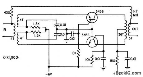
CAPACITIVE_TRANSISTOR_SYNC_LOCK
Published:2009/7/20 20:36:00 Author:Jessie
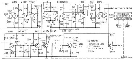
Provides stable sync lock of signal generator against noise interference on tv station relay lines.-Y. Fujimura and N. Mii, Automatic Frequency Control with Reactance Transistors, Electronics, 33:40, p 97-99. (View)
View full Circuit Diagram | Comments | Reading(1379)
CONTINUITY_CHECKER
Published:2009/7/20 20:35:00 Author:Jessie

National LM3909 IC operating from 1.5-V cell provides enough audio power to drive loudspeaker when probes are shorted by resistance up to about 100 ohms. By probing two points in rapid succession, small differences in resistance can be detected by noticeable differences in tone; this feature is useful for identifying windings of transformers.- Linear Applications, Vol. 2, National Semiconductor, Santa Clara, CA, 1976, AN-154, p 4-5. (View)
View full Circuit Diagram | Comments | Reading(0)
EEG_WAVEFORM_ZERO_DETECTOR
Published:2009/7/20 20:34:00 Author:Jessie
Uses Schmitt triggers to produce output of one value when input signal exceeds preset reference, and produces output of one other value when input signal is less than reference value.-C. J. Zaander, Computer Analyzes Brain Waveforms, Electronics, 31:29, p 68-72. (View)
View full Circuit Diagram | Comments | Reading(1077)
MESA_TRANSISTOR_TUNER_OSCILLATOR
Published:2009/7/20 20:34:00 Author:Jessie
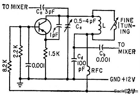
Uses common-base transistor connection, which is regenerative at high frequencies. Additional feedback capacitance between emitter and collector assures dependable oscillation. With emitter current of 2 ma, circuit can supply about 20 times the 300 microwatts required by mixer. Sliding-core coil gives 2:1 change in inductance for fine tuning.-H. F. Cooke, Designing Tv Tuners with Mesa Transistors, Electronics, 33:15, p 64-69. (View)
View full Circuit Diagram | Comments | Reading(651)
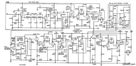
THREE_OUTPUT_3_KC_OSCILLATOR
Published:2009/7/20 20:34:00 Author:Jessie
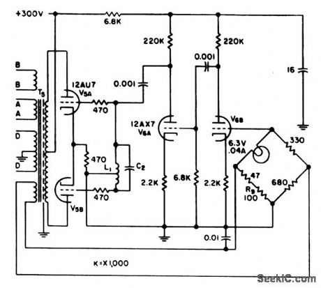
L-C oscillator provides carrier voltages of 4 V rms at 3 kc to blood-volume servo amplifier and to venous and arterial pressure indicator-Amplitude stabilization is achieved by bridge feedback network using filament-type lamp as nonlinear element in one bridge arm.-R. Schild and N. Wesson, Servo Circuit Controls Artifidal Heart, Electronics, 31:15, p 73-75. (View)
View full Circuit Diagram | Comments | Reading(690)
AC_OHMMETER
Published:2009/7/20 20:33:00 Author:Jessie

Optoisolator circuit operating from single battery develops alternating current for measuring resistance of soils and construction materials without errors due to polarization and earth-current effects. 555 IC timer controls output at frequency determined by R1, R2, and CT, R1 is made very much less than R2 but should not be below about 1 K. Frequency value is 1.44/(R1 + 2R2)CT Output switching matrix is controlled by timer so OC1 and OC4 are on for one half-cycle and OC2 and OC3, are on for other half. Output current is independent of frequency and duty cycle up to 150 Hz. With Monsanto MCT-2 optoisolators, R3 and R4, are 330 ohms and R5-R8 are each 22K.-D. J. Beckwitt, AC Ohmmeter Provides Novel Use for Opto-Isolators, EDN Magazine, July 5, 1974, p 70. (View)
View full Circuit Diagram | Comments | Reading(1005)
INDUCTIVE_TRANSI_STOR_SYNC_LOCK
Published:2009/7/20 20:33:00 Author:Jessie
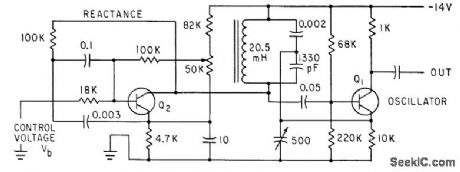
D-c bias of inductive-reactance transistor Q2 is controlled by modulating voltage from oscillator Q1.-Y. Fujimura and N. Mil, Automatic Frequency Control with Reactance Transistors, Electronics, 33:40, p 97-99. (View)
View full Circuit Diagram | Comments | Reading(657)
TWO_TRANSISTOR_CARDIAC_PACEMAKER
Published:2009/7/20 20:33:00 Author:Jessie

Produces triggering pulses that stimulate heartbeats during surgery. Repetition rate is determined by C1 and R1. Pulse duration is 4 millisec, with 8-V peak that sends 16 ma through 500-ohm load.-W. E. Gilson and H. F. Klinge, Cardiac Pacemaker Triggers Heartbeats, Electronics, 34;40, p 80. (View)
View full Circuit Diagram | Comments | Reading(4364)
CCTV_10_MC_REPEATER
Published:2009/7/20 20:31:00 Author:Jessie
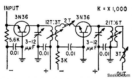
Has gain characteristics to match losses in 0.5 mile of coaxial cable. Mismatching is used at input and between stages to stabilize gain and cut if down to required 18 db at 15 Mc.-L. G. Schimpf, Carrier Transmission for Closed-Circuit Television, Electronics, 32:24, p 66-68. (View)
View full Circuit Diagram | Comments | Reading(662)
LOW_VOLTAGE_OHMMETER
Published:2009/7/20 20:31:00 Author:Jessie

Combines stable constant-current source U1-CR1-RY with DC amplifier U2 having gain of 10 to keep applied voltage down to 0.1V. Output is linearly proportional to unknown resistance. Resistances well below 1 ohm can be measured accurately, U2 scales 0-100 mV unknown voltage to 0-1 V at output, so 1K resistor under test can be read as 1.000K on DVM scale. U2 should be offset-nulled to eliminate zero error, for best low-scale accuracy, by shorting input and adjusting R4 for 0.000 V out of U2. Full-scale calibration involves trimming individual range values ofRY for correct output, while using reference value for RX. Fuse and clamp diodes protect range resistors, and R5 protects opamp.-W. Jung, An IC Op Amp Update, Ham Radio, March 1978, p 62-69. (View)
View full Circuit Diagram | Comments | Reading(1117)
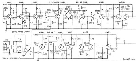
ULTRASONIC_OSCILLATOR_KEYER
Published:2009/7/20 20:31:00 Author:Jessie
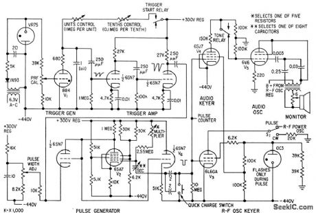
Generates keying pulses up to 2 sec wide at prf down to 0.1 pps. Oscillator cutoff bias is gated off during pulse operation and switched off during c-w operation. Pulse repetition generator V1 is relaxation oscillator with trigger period variable in 0.1-sec steps from 0.1 to 10.9 sec. Fast-recovery phantastron pulse generator 1/2 allows precise pulsing up to 90% duty cycle, with pulse lengths from 0.005 to 2 sec.-B. J. Cosman amd T. F.Hueter, Instrumentation for Ultrasonic Neurosurgery, Electronics, 32:20, p 53-57. (View)
View full Circuit Diagram | Comments | Reading(811)
-15_V_1_A_REGULATED_POWER_SUPPLY
Published:2009/7/9 2:51:00 Author:May
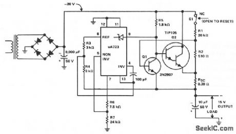
The supply receives -20 V from the rectifter/ftlter which is fed to the collector of the Darlington pnp pass transistor, a TIP105. The base drive to the TIP105 is supplied through resistor R5. The base of the TIP105 is driven from VZ terminal at pin 9, which is the anode of a 6.2-V zener diode that connects to the emitter of the μA723 output control transistor. The method of providing the positive feedback required for foldback action is shown. This technique introduces positive feedback by increased current flow through resistors R1 and R2 under short-circuit conditions. This forward biases the base-emitter junction of the 2N2907 sensing transistor, which reduces base drive to the TIP105. (View)
View full Circuit Diagram | Comments | Reading(811)
_15_V_1_A_REGULATED_POWER_SUPPLY
Published:2009/7/9 2:50:00 Author:May
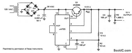
The supply receives +20 Vdc from the rectifier/filter section. This is applied to pins 11 and 12 of the μA723, as well as to the collector of the 2N3055 series-pass transistor. The output voltage is sampled through R1 and R2, providing about 7 V with respect to ground at pin 3. The reference terminal at pin 6 is tied directly to pin 5, the noninverting input of the error amplifter. For fine trimming the output voltage, a potentiometer can be installed between R1 and R2. A 100-μF capacitor from pin 13 to pin 4 furnishes gain compensation for the amplifter.Base drive to the 2N3055 pass transistor is furnished by pin 10 of the μA723. Since the desired output of the supply is 1 A, maximum current limit is set to 1.5 A by resistorRSC whose value is 0.433 Ω.A 100-μF electrolytic capacitor is used for ripple voltage reduction at the output. A 1-KΩ output resistor provides stability for the power supply under no-load conditions. The 2N3055 pass transistor must be mounted on an adequate heatsink. (View)
View full Circuit Diagram | Comments | Reading(1697)
LIQUID_LEVEL_SENSOR
Published:2009/7/9 2:49:00 Author:May
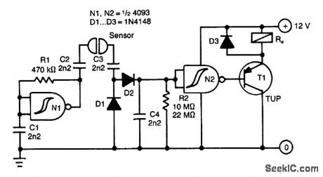
This circuit uses an ac-sensing signal to elimi-nate electrolytic corrosion. The ac signal is rectifted and used to drive a transistor that controls a relay. (View)
View full Circuit Diagram | Comments | Reading(1312)
The heating magnetic mixer (2)
Published:2011/7/21 21:58:00 Author:qqtang | Keyword: heating magnetic mixer

Here is to introduce the heating magnetic mixer which has the functions of stepless speed regulation mixing, constant temperature auto control, stepless temperature regulation and timing alarm, etc, it can be used in the labs chemical and steel area.The working principle of the circuit The heating magnetic mixer consists of the power supply circuit, mixing motor control circuit, heating temperature regulation circuit, mixing circuit motor speed regulation circuit, timing alarm circuit and timing control circuit, see as figure 8-139.
(View)
View full Circuit Diagram | Comments | Reading(634)
PREAMPLIFIER_FOR_MAGNETIC_PHONO_CARTRIDGES
Published:2009/7/9 2:49:00 Author:May

This amplifier is intended to be added to preamplifiers that have no phono input. Such a phono input is required for normal record players with a dynamic pick-up, of which millions are still around. Moreover, the amplifier does not only bring the output of the pick-up to line level, it also adds the correction to the fre-quency response (according to RIAA requirements).
When recording gramophone records, the frequency characteristic is lifted at the high end. This lift must be countered in the playback (pre)amplifier. The corrections to the frequency response characteris-tic are according to a norm set by the Record Industries Association of America (RIAA) and also by the IEC.
The corrective curve provided 'oy the amplifier is shown in the graph (bold line). The thin line shows the ideal corrective curve. The sharp bends in this at 50 and 500 Hz are nearly obtained in the practical curve by network R3lC2; just above 2 kHz is approached in practice by filter R5/R6/C3. The arrangement of R3/C2 in the feedback loop pf IC1 gives noticeably better results than the usual (passive) filter approach.
Circuit IC1 provides a dc amplification of 40 dB, which drops to about 20 dB when the frequency rises above 500 Hz. To minimize the (resistor) noise and the load of the op amp at higher frequencies, the value of R3 is a compromise. The associated polystyrene capacitor, CZ, should have a tolerance of 1 to 2%.
To raise the 2-mV output of the dynamic pick-up to line level at 1 kHz, linear amplifier IC2 has been added. This stage has a gain of 22 dB, so a signal of 250 mV is available at its output.
Capacitors C4/C5 at the output, in conjunction with the input impedance of the following preamplifier, form a high-pass filter with a cut-off frequency of 20 Hz; this serves to suppress any rumble or other low frequency noise. The value of C1 is normally given in the instruction booklet of the dynamic pick-up.
The power supply for the amplifier must be of good quality. Particularly, the transformer should be class Al with a small stray magnetic field.
When the amplifier is built into the record player (best), the power supply should not be included unless it is very well screened; otherwise, hum is unavoidable. (View)
View full Circuit Diagram | Comments | Reading(2485)
FAST_SYMMETRICAL_ZENER_CLIPPER
Published:2009/7/9 2:48:00 Author:May

The problem with using two zeners back to back in series to get symmetrical clamping is that the knee of the zener characteristics is rather sloppy. Also, charge storage in the zeners causes speed problems and the zeners will have slightly different knee voltages, so the symmetry will not be all that good. This circuit overcomes these problems.By putting the zener inside a diode bridge, the same zerxer voltage is always experienced. The voltage errors caused by the diodes are much smaller than those caused by the zener. Also, the charge storage of the bridge is much less. By biasing the zener ON all the time, the knee appears to be much sharper. (View)
View full Circuit Diagram | Comments | Reading(576)
COLOR_VIDEO_AMPLIFIER
Published:2009/7/9 2:47:00 Author:May
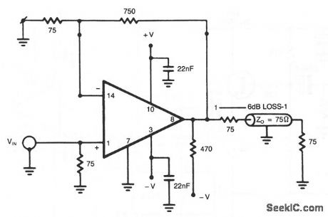
The NE5539 wideband op amp is easily adapted for use as a color video amplifier. The gain varies less than 0.5% from the bottom to the top of the stainase. The maximum differential phase is approximately + 0.1 °.The amplifier circuit was optimized for a 75-Ω input and output termination impedance for a gain of approximately 10 (20 dB). (View)
View full Circuit Diagram | Comments | Reading(0)
CCTV_RECEIVING_TERMINAL
Published:2009/7/20 20:31:00 Author:Jessie
Used with repeater (not shown) that makes up for loss in last section of cable. Amplifier then raises level about 10 db. Selective negative feedback improves transmission characteristic over bandwidth of 3 to 17 Mc.-L. G. Schimpf, Carrier Transmission for Closed-Electronics, Television, Electronics 32:24, p 66-68.
(View)
View full Circuit Diagram | Comments | Reading(607)
| Pages:906/2234 At 20901902903904905906907908909910911912913914915916917918919920Under 20 |
Circuit Categories
power supply circuit
Amplifier Circuit
Basic Circuit
LED and Light Circuit
Sensor Circuit
Signal Processing
Electrical Equipment Circuit
Control Circuit
Remote Control Circuit
A/D-D/A Converter Circuit
Audio Circuit
Measuring and Test Circuit
Communication Circuit
Computer-Related Circuit
555 Circuit
Automotive Circuit
Repairing Circuit