
Circuit Diagram
Index 909
AUDIBLE_OHMMETER_1
Published:2009/7/20 20:11:00 Author:Jessie

Volume and/or pitch of one-transistor audio oscillator varies with resistance across test terminals, to give audible indication of continuity and relative resistance without looking at meter. Can also be used as transistor and diode tester, signal injector, code practice oscillator, and CW monitor. Oscillator uses transistor-type transformer having center tapped windings, connected as shown to give three-winding transformer. Operates from two 1.5-V cells in series. Will respond to resistance values from short to about 100K. Volume in-creases and pitch rises as resistance is increased. For very low resistance, tone resembles croaking of frog.-Build the EI Sapo Tester, 73 Magazine, Dec. 1977, p 184-185. (View)
View full Circuit Diagram | Comments | Reading(981)
MOISTURE_TESTER
Published:2009/7/20 20:06:00 Author:Jessie

Simple probe tells when plants need watering. Amount of moisture and minerals in soil together determine current available for LED. Almost full brilliance indicates adequate moisture, and no illumination means plant needs water badly. Probe can be No. 14 wire filed to point and centered with epoxy in 3/16-inch copper tubing, or simply two stiff probe wires about 1 inch apart.-W. L. MacDowell, The Violet Tester, 73 Magazine, May 1975, p 52-53. (View)
View full Circuit Diagram | Comments | Reading(731)
20_W_AUDIO_AMPLIFIER
Published:2009/7/9 2:20:00 Author:May
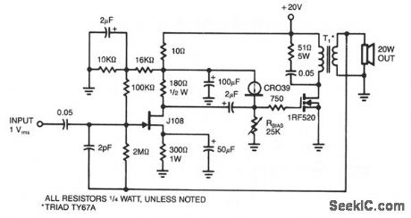
This amplifier delivers 20 W into an 8-Ω load using a single IRF520 driving a transformer coupled output stage.This circuit is similar to the audio output stage used in many inexpensive radios and phonographs.Distortion is less than 5% at 10 W,using very little feedback (3%),with the IRF520 biased at 3 A. (View)
View full Circuit Diagram | Comments | Reading(3263)
FLICKER_LIGHT
Published:2009/7/9 2:20:00 Author:May

This circuit will produce a flicker light effect with an ordinary incandescent lamp. Three UJT relaxation oscillators fire the SCR in a pattern. (View)
View full Circuit Diagram | Comments | Reading(1417)
BRIDGE_FOR_01_5_OHMS
Published:2009/7/20 20:05:00 Author:Jessie

Set meter reading to zero with multiturn pot R1 when test leads are shorted. Simple one-point calibration is made by using known low resistance for about midrange value and setting meter to convenient scale marking by adjusting R2. Calibration curve is then made for meter scale by using other normal resistances.-J. Schultz, An Ohmmeter Potpourri, CQ, June 1978, p 32-33. (View)
View full Circuit Diagram | Comments | Reading(723)
500_MEGOHM_LINEAR_SCALE_OHMMETER
Published:2009/7/20 19:59:00 Author:Jessie


Resistance multiplier using 741 opamp reduces current drain when measuring low resistance values(below 10 ohms), LEDs indicate voltage difference between outputs of A1 and A2. as guide for minimizing difference during measurement. RS sets meter for full-scale deflection when measuring resistor value equal to standard RC.-E.H. Armanino, Extending the Range of the Linear-Scale Ohmmeter,Electronics.Dec.22.1977,p93-94. (View)
View full Circuit Diagram | Comments | Reading(2473)
AUDIBLE_OHMMETER
Published:2009/7/20 19:59:00 Author:Jessie

Circuit is built around 555 timer. Resistance detection range is from 0 ohms to about 10 megohms. At high end of range, output is series of clicks from loudspeaker, and at low end is high-pitched tone. Intermediate resistance values produce different tones. Current through unknown resistance is only a few microamperes, so semiconductor junctions can be checked without damage. R2 80 sets frequency for 0 ohms. Can also be used as Speaker code practice oscillator if RX terminals are shorted and ground lead of pin 1 is keyed.-J.Schultz, An Ohmmeter Potpourri, CQ, June 1978, p 32-33. (View)
View full Circuit Diagram | Comments | Reading(875)
65_240_Hz
Published:2009/7/20 19:57:00 Author:Jessie

Output of 65-240 kHz crystal oscillator is divided by 1000 in three SN7490s to give 65-240 Hz tone required for access to amateur FM repeater. Choose crystal to give exactly desired frequency Q1 and Q2 are MPS6513, and Q3 is 2N1613. Supply can be 9 to 15 VDC from transceiver or from 9-V battery.-P. H. Wiese, Rock Solid Subaudible Tone Generator, 73 Magazine, April 1974, p 79-81. (View)
View full Circuit Diagram | Comments | Reading(690)
FLASHINGLED_CONTROLLER
Published:2009/7/9 2:18:00 Author:May

The LED with integrated flasher is connected in series with the base-emitter junction of transistor T1. Thus, the load connected to K2 is switched on and off in rhythm with the flash rate. This load can be a relay or a lamp.
The maximum collector current of the transistor (of the BD139=750mA) must not be exceeded. If that is not sufficient, a power Darlington can be used, which will give some amperes. The current drawn by the circuit under no-load conditions amounts to 20mA. (View)
View full Circuit Diagram | Comments | Reading(888)
TIME_OUT_TIMER
Published:2009/7/20 19:55:00 Author:Jessie

Prevents unnecessary repeater timeouts by generating warning tone in loudspeaker of mobile transceiver when transmitter is on too long. Normal push-to-talk line is broken and connected to points A and D. Pushing talk button starts timer. Time in seconds is 1.1 R3C3, with R3 in megohms and 03 in microfarads. Thus, 1 megohm and 27μF give 30 s, while 2 megohms and 81μF give 180 s.-J. A. Kvochick, Keeping the Wind Down, 73 Magazine, Feb. 1977, p 50. (View)
View full Circuit Diagram | Comments | Reading(870)
ACCESS_TONE_GENERATOR
Published:2009/7/20 19:54:00 Author:Jessie

Produces audio burst for 0.5 s at frequency determined by R1 and C1, for use with FM transceiver as subaudible tone generator to access repeaters. Provides buffered outputs of square waves as well as triangle waves. Uses NE566 function generator as voltage-controlled oscillator having excellent stability and linearity, R1 should be between 2K and 20K. SCR should be type that triggers at 70μA.-E. Kanter, PLL IC Applications for Hams, 73 Magazine, Sept. 1973, p 47-49. (View)
View full Circuit Diagram | Comments | Reading(2061)
HYBRID_POWER_AMPLIFIER
Published:2009/7/9 2:16:00 Author:May
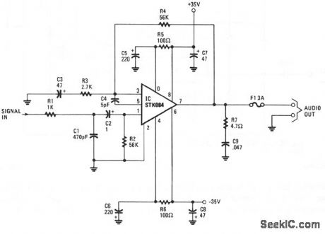
The input is ac coupled to the amplifier through C2, which blocks dc signals that might also be present at the input. The R1/C1 combination forms a low-pass filter, which eliminates unwanted high-frequency signals by bypassing them to ground when they appear at the circuit input, which has an impedance of about 52 Ω. The gain of the amplifier is set at about 26 dB by resistors R3 and R4. The R5/C5/C7 combination on the positive supply and its counterpart R6/C6/C8 on the negative supply provides power-supply decoupling. R7 and C9 together prevent oscillation at the output of the amplifier. From that point, the amplifier's output signal is direct coupled to the speaker through a 3-A fuse, F1. The dc output of the amplifier at pin 7 is 0 V, so no dc current flows through the speaker. Should there be a catastrophic failure of the output stage, fuse F1, which should be a fast-acting type, prevents dc from flowing through the speaker. (View)
View full Circuit Diagram | Comments | Reading(818)
ACCESS_TONE_BURST
Published:2009/7/20 19:53:00 Author:Jessie

Generates 1-s tone burst at specified audio frequency such as 1800 Hz each time transmitter is energized, to pro-vide access to a desired repeater. Uses CMOS CD4001AE quad NOR gate, which is small enough so entire circuit can be fitted in micro-phone housing. Gates are connected as astable MVBR, with ON time of tone burst determined by R2C2 time constant, triggered by push-to talk switch (PTT). Large capacitor C3 powers MVBR during burst, with capacitor normally charged to 12 V through PTT circuit during receive. Supply voltage is taken through Prr relay in transmitter.-G. Hinkle, Tone-Burst Genera-tor for Repeater Accessing, Ham Radio, Sept, 1977, p 68-69. (View)
View full Circuit Diagram | Comments | Reading(1114)
OPTICAL_PUSH_PULL_COUPLING
Published:2009/7/20 12:35:00 Author:Jessie

Two gallium arsenide light sources and two high-speed silicon photoconductors provide push-pull optical coupling between integrated-circuit flip-flop ond buffer, with two transistors in push-pull amplifier overcoming losses of optical coupling.-T. E. Bray, Switching With Light, Electronics, 38:22, p 58-65. (View)
View full Circuit Diagram | Comments | Reading(670)
LIGHT_ACTIVATED_SCR_TIME_DELAY
Published:2009/7/20 12:32:00 Author:Jessie

Boot-strapped unijunction transistor interrupts load current at desired delay interval (determined by R1 and C1) after short pulse of light hits glass-window scr L8U.-E. K. Howell, Light-Activated Switch Expands Uses of Silicon-Controlled Rectifiers, Electronics, 37:15, p 53-61. (View)
View full Circuit Diagram | Comments | Reading(788)
FLASH_ACTUATED_SCR_DELAY
Published:2009/7/20 12:29:00 Author:Jessie

Fractional-cycle light pulse fires glass-window scr at any phase angle, while values of circuit components determine number of cycles of conduction before turn off at zero current.-E. K. Howell, Light-Activated Switch Expands Uses of Silicon-Controlled Rectifiers, Electronics, 37:15, p 53-61. (View)
View full Circuit Diagram | Comments | Reading(880)
PHOTOREED_OSCILLATOR
Published:2009/7/20 12:28:00 Author:Jessie

Gives good sinewave output at reed frequency, using phototransistor to sense chopped light and transistor to boost output voltage. Can be used for remote control, telemetry, and logic functions.-Frequency-Sensitive Control Uses Light, Electronics, 34:36, p 88-91. (View)
View full Circuit Diagram | Comments | Reading(555)
PHOTODIODE_AMPLIFIER
Published:2009/7/20 12:27:00 Author:Jessie

Used with transmitted-light encoder disk to produce pulses with correct amplitude and rise time to drive logic circuit.-F. W. Kear, How to Select Shaft-Position Encoders, Electronics, 35:35, p 48-51. (View)
View full Circuit Diagram | Comments | Reading(0)
ILLUMINATION_TELEMETER
Published:2009/7/20 12:26:00 Author:Jessie

Prf rate of blocking oscillator, controlled by photocell output, can be transmitted over telephone lines to give accurate remote indication of day-light or other light intensity. D1, V2B, and meter provide local indication. Maximum illumination gives highest prf.-E. F. Hasler and G. Spurr, Ways to Measure Light Intensity at a Distance, Electronics, 32:29, p 48-49. (View)
View full Circuit Diagram | Comments | Reading(508)
SQUARE_WAVE_GENERATOR
Published:2009/7/20 12:08:00 Author:Jessie

Intensity of light sets pulse and interpulse periods in range from 0.2 to 300 sec, using Schmitt trigger Q1-Q2. Capacitor C is charged and discharged through diodes D1 and D2 consisting of collector-base junctions of 2N1393 phototransistors.-A. K. Horvath, Photodiodes Control Pulse Intervals, Electronics, 38:11, p 72. (View)
View full Circuit Diagram | Comments | Reading(1)
| Pages:909/2234 At 20901902903904905906907908909910911912913914915916917918919920Under 20 |
Circuit Categories
power supply circuit
Amplifier Circuit
Basic Circuit
LED and Light Circuit
Sensor Circuit
Signal Processing
Electrical Equipment Circuit
Control Circuit
Remote Control Circuit
A/D-D/A Converter Circuit
Audio Circuit
Measuring and Test Circuit
Communication Circuit
Computer-Related Circuit
555 Circuit
Automotive Circuit
Repairing Circuit