Amplifier Circuit
HYBRID_POWER_AMPLIFIER
Published:2009/7/9 2:16:00 Author:May | From:SeekIC

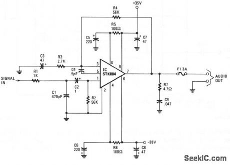
The input is ac coupled to the amplifier through C2, which blocks dc signals that might also be present at the input. The R1/C1 combination forms a low-pass filter, which eliminates unwanted high-frequency signals by bypassing them to ground when they appear at the circuit input, which has an impedance of about 52 Ω. The gain of the amplifier is set at about 26 dB by resistors R3 and R4. The R5/C5/C7 combination on the positive supply and its counterpart R6/C6/C8 on the negative supply provides power-supply decoupling. R7 and C9 together prevent oscillation at the output of the amplifier. From that point, the amplifier's output signal is direct coupled to the speaker through a 3-A fuse, F1. The dc output of the amplifier at pin 7 is 0 V, so no dc current flows through the speaker. Should there be a catastrophic failure of the output stage, fuse F1, which should be a fast-acting type, prevents dc from flowing through the speaker.
Reprinted Url Of This Article:
http://www.seekic.com/circuit_diagram/Amplifier_Circuit/HYBRID_POWER_AMPLIFIER.html
Print this Page | Comments | Reading(3)

Article Categories
power supply circuit
Amplifier Circuit
Basic Circuit
LED and Light Circuit
Sensor Circuit
Signal Processing
Electrical Equipment Circuit
Control Circuit
Remote Control Circuit
A/D-D/A Converter Circuit
Audio Circuit
Measuring and Test Circuit
Communication Circuit
Computer-Related Circuit
555 Circuit
Automotive Circuit
Repairing Circuit
Code: