
Circuit Diagram
Index 902
ANALOG_EXPANDED_SCALE_METER_FOR_AUTOS
Published:2009/7/9 3:52:00 Author:May

Zener diode D1 is used to suppress the ftrst 6 V of the scale, which gives a meter reading of 6 to 8 V-useful for automotive electrical system monitoring. (View)
View full Circuit Diagram | Comments | Reading(628)
VARIABLE-CAPACITANCE_DIODE_SPARKED_VCO
Published:2009/7/9 3:52:00 Author:May

You can transform a 741S124 multivibrator into a wideband VCO by replacing it conventional ftxed capacitor with a variable-capacitance diode. The only disadvantage of this scheme is the 30-V biasing volt-age that the diode requires. Capacitors C1 and C2 couple the Philips BB909A variable-capacitance diode to the 74S124. R1 and R2 are large enough to isolate ground and control voltages from the timing capacitors. Resistors R3 and R4 form a voltage divider for the 74S124's control input. (View)
View full Circuit Diagram | Comments | Reading(1088)
HIGH_GAIN_PHASE_CONTROL
Published:2009/7/20 6:25:00 Author:Jessie
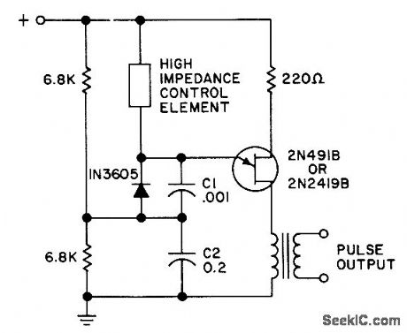
Use of two different sizes of charging capacitors in series increases effective gain up to 10,000 times that of conventional ujt/scr phase-control circuit. Eliminates amplification.- Transistor Manual, Seventh Edition, General Electric Co., 1964, p 332. (View)
View full Circuit Diagram | Comments | Reading(686)
DIGITAL_FUEL_GAUGE
Published:2009/7/9 3:51:00 Author:May

This circuit uses a digital voltmeter (formed from IC1 and IC3) to display fuel quantity as a percentage of a full tank. In order to work with two kinds of fuel sensors, low resistance = full. Where higher resistance full, IC2 forms a dc amplifier that has both inverting (path A) or noninverting (path B) outputs, and calibration adjustments for each path. (View)
View full Circuit Diagram | Comments | Reading(3424)
AUDIO_FUNCTION_GENERATOR
Published:2009/7/9 3:51:00 Author:May

Using an EXAR XR2206, this generator will produce sine, square, and triangular waves from 10 Hz to 100 kHz. U1 is the XR2206 chip, R7 controls frequency, and 55 through 58 select the frequency range. U3 produces a TTL-compatible square-wave output, while U3C and D produce a sync signal for scope use. U2 is a frequency/voltage converter that is used to drive analog meter M1, which reads the generator frequency. (View)
View full Circuit Diagram | Comments | Reading(7540)
WAVEFORM_GENERATOR_STABLE_VCO
Published:2009/7/9 3:49:00 Author:May

In this circuit, a waveform generator is used as a stable VCO in a Phase-Locked Loop (PLL). (View)
View full Circuit Diagram | Comments | Reading(1073)
DIGITAL_VACUUM_GAUGE
Published:2009/7/9 3:47:00 Author:May

A bridge circuit is used to produce a signal from the output of vacuum sensor IC1. IC2b provides about a 0.2 V offset for IC4, the A/D converter. IC2b and d are voltage followers that drive differential amp IC2a. The output of this circuit is used to drive IC4 and IC1, the display drivers. (View)
View full Circuit Diagram | Comments | Reading(1626)
ELECTRONIC_VOICE_SUBSTITUTE
Published:2009/7/9 3:45:00 Author:May

The 555 acts as the tone generator configured in the astable mode. Its pin 3, square-wave output is transformed into a triangle wave by R1 and C2. The voice's pitch is controlled by R1. Transistor Q1 can be 2N1086, 2N1091, or any other equivalent npn germanium type. Sounds are amplified by the 741, and the IC's output drives the transistor to saturation. When the transistor is in the saturated state, the triangle wave is able to reach the speaker, and your new voice can be heard. (View)
View full Circuit Diagram | Comments | Reading(899)
AUTOMOTIVE_ELECTRICAL_TESTER
Published:2009/7/9 3:45:00 Author:May


This little tester is useful for checking vehicle electrical circuits. Two LEDs indicate whether one of the clips is connected to the positive supply line (red) or to ground (green).
The unit is powered by the vehicle battery. It is advisable to terminate the unit into two insulated heavy-duty crocodile clips. These enable connection to be made directly to the battery or to terminals on the fuse box.It is also possible to terminate it into a suitable connector that fits into the cigarette lighter socket. If a sharp needle is soldered to one of the terminals, it is possible to check insulated wiring-but only those that carry 12 V.
Although the needle pierces the insulation, it does not damage it. (View)
View full Circuit Diagram | Comments | Reading(961)
36_MHz_RFamplifier_using_a_3N211_dual_gate_MOSFET
Published:2009/7/20 23:45:00 Author:Jessie
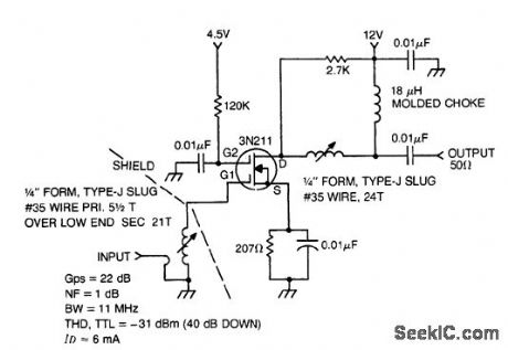
36 MHz RFamplifier using a 3N211 dual-gate MOSFET(courtesy Texas Instruments Incorporated). (View)
View full Circuit Diagram | Comments | Reading(1214)
WATER_TEMPERATURE_GAUGE
Published:2009/7/9 3:41:00 Author:May

This gauge is similar to the miscellaneous temperature gauge, except that a thermostat is used as a sensing element. (View)
View full Circuit Diagram | Comments | Reading(1144)
LAMP_TRIGGERED_SCR_GIVES_VARIABLE_PHASE_CONTROL_OF_POWER
Published:2009/7/20 7:34:00 Author:Jessie

Miniature 2128 lamp with low-mass filament triggers light-activated scr in 1 millisec when lamp is across scr and in about 3 cycles at low a-c lamp voltage. Potentiometer thus provides phase control of scr for dimming 25-w lamp or equivalent-wattage load.-E. K. Howell, Light-Activated Switch Expands Uses of Silicon-Controlled Rectifiers, Electronics, 37:15, p 53-61. (View)
View full Circuit Diagram | Comments | Reading(1119)
45_MHz_RF_post_amplifier_using_two_3N204_dual_gate_MOSFETs
Published:2009/7/20 7:34:00 Author:Jessie
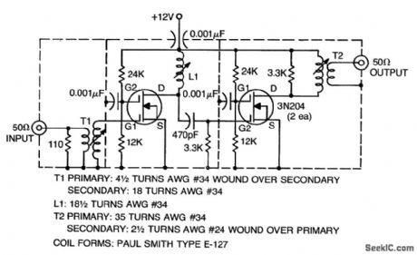
45 MHz RF post amplifier using two 3N204 dual-gate MOSFETs (courtesy Texas Instruments Incorporated). (View)
View full Circuit Diagram | Comments | Reading(966)
AGC_FOR_PHOTODETECTOR_AMPLIFIER
Published:2009/7/20 7:33:00 Author:Jessie

Holds photodetector output signal constant within 2 db for 4-db variation in ambient light level. -P. H. Sydenham, Photodetector Gain Control Aids Signal Discrimination, Electronics, 38:23, p 111. (View)
View full Circuit Diagram | Comments | Reading(684)
25_watt_UHF_microstrip_amplifier_for_450_to_470_MHz
Published:2009/7/20 7:32:00 Author:Jessie

25-watt UHF microstrip amplifier for 450 to 470 MHz (courtesy Motorola Semiconductor Products Inc.). (View)
View full Circuit Diagram | Comments | Reading(1398)
Amplitude_modulator_using_an_AM1545G_wide_band_amplifier_
Published:2009/7/20 7:31:00 Author:Jessie
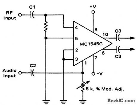
Amplitude modulator using an AM1545G wide-band amplifier (courtesy Motorola Semiconductor Products Inc.). (View)
View full Circuit Diagram | Comments | Reading(840)
SINGLE_SUPPLY_FREQUENCY_VOLTAGE_CONVERTER
Published:2009/7/9 3:40:00 Author:May
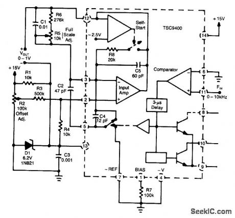
A Teledyne TSC9400 provides 0-to-1-V output from a 0-to-10-kHz input.A single +15-V supply is used,Linearity is 0.25% to 10 kHz. (View)
View full Circuit Diagram | Comments | Reading(821)
ALLOPHONE_GENERATOR
Published:2009/7/9 3:40:00 Author:May

The circuit, a general-purpose system with many uses, vocalizes 59 allophones contained in the speech processor. After filtering and amplification, its pulse-code-modulated output can drive an 8-Ω speaker. The processor's address pins, A1 to A6, define 64 speech-entry points.Closing the test switch to the NAND gate lowers its output, thereby loading an address and triggering the ALD input for an allophone cycle. The CD4520 dual binary counter, IC2, counts from 0 to 63 in binary code until its Q7 output resets it on the number 64 count. To generate a phrase, just add an EPROM between IC2 and IC3 that contains a program for a predetermined sequence of allophones. (View)
View full Circuit Diagram | Comments | Reading(997)
DIGITAL_OIL_PRESSURE_GAUGE
Published:2009/7/9 3:39:00 Author:May

This gauge uses a sensor in conjunction with R1 to develop a dc voltage proportional to oil pressure. IC1 and IC2 form a two-digit DVM. Q1 and Q2 are display selectors for the multiplexed display. IC1 provides the necessary +5V to the circuitry. Calibration is via R11 and zero adjust via R17. (View)
View full Circuit Diagram | Comments | Reading(1009)
GENERAL_PURPOSE_PREAMP
Published:2009/7/9 3:35:00 Author:May
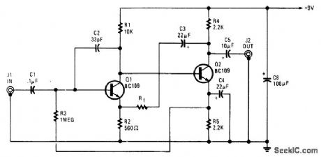
This amplifier is useful for audio and video applications. Gain is set by Rf and the voltage gain of this amplifier is approximately 1 +Rf/560, where Rf is in ohms. Bandwidth depends on gain selected, but typi-cally it is several MHz. Rf=5.1 kΩ, which produces a gain of 10x (20 dB) voltage. (View)
View full Circuit Diagram | Comments | Reading(974)
| Pages:902/2234 At 20901902903904905906907908909910911912913914915916917918919920Under 20 |
Circuit Categories
power supply circuit
Amplifier Circuit
Basic Circuit
LED and Light Circuit
Sensor Circuit
Signal Processing
Electrical Equipment Circuit
Control Circuit
Remote Control Circuit
A/D-D/A Converter Circuit
Audio Circuit
Measuring and Test Circuit
Communication Circuit
Computer-Related Circuit
555 Circuit
Automotive Circuit
Repairing Circuit