
Circuit Diagram
Index 913
SCOPE_EXTENDER
Published:2009/7/9 1:54:00 Author:May

The adapter allows four inputs to be displayed simultaneously on a single trace scope. For low-frequency signals, less than 500 Hz, the adapter is used in the chop mode at a frequency of 50 kHz. The clock can be run faster, but switching glitches and the actual switching time of the DG201A limit the maximum frequency to 200 kHz. High frequencies are best viewed in the alternate mode, with a clock frequency of 200 Hz. When the clock is below 100 Hz, trace flicker becomes objectionable. One of the four inputs is used to trigger the horizontal trace of the scope.
(View)
View full Circuit Diagram | Comments | Reading(594)
PREFERRED__150_V_D_C_REGULATOR
Published:2009/7/20 7:42:00 Author:Jessie
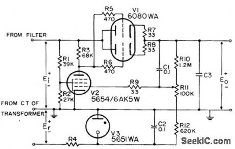
Provides 1% output voltage regulation under normal line and load variations of military equipment. Minimum value of C3 is 2 mfd. Value of R4 depends on reference voltage Er, which should be minimum of -150 v d-c. Minimum input voltage is 200 v d-c.-NBS, Handbook Preferred Circuits Navy Aero-nautical Electronic Equipment, Val. 1, Electronic Tube Circuits, 1963, PC 1, p 1-2. (View)
View full Circuit Diagram | Comments | Reading(0)
POSITIVE_REFERENCE_REGULATOR_1
Published:2009/7/20 7:40:00 Author:Jessie
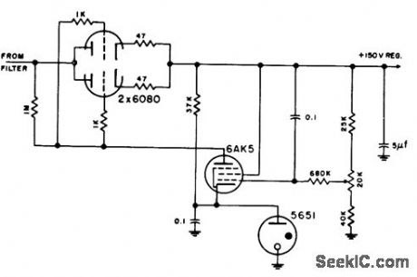
Has self-contained 150-v positive reference potential for pentode regulator, but gives only marginal operation.-NBS, Handbook Preferred Circuits Navy Aeronautical Electronic Equipment, Vol. 1, Electron Tube Circuits, 1963, p N2-4. (View)
View full Circuit Diagram | Comments | Reading(662)
LOW_DISTORTION_AMPLIFIER_COMPRESSOR
Published:2009/7/9 1:53:00 Author:May

Designers can build a 15-dB compressor with a miniature lamp and a current-feedback amplifier. The circuit possesses extremely low distortion at frequencies above the lamp's thermal time constant. This means that distortion is negligible from audio frequencies to beyond 10 MHz. There's also relatively little change in phase versus gain compared to other automatic gain-control circuits. Lastly, the circuit has many instrumentation, audio, and high-frequency applications as a result of its low distortion and small phase change.
The AD844 op amp is a perfect fit for this application because it's a current-feedback amplifier. Each stage of the circuit, U2, lamp, and feedback resistor compresses an ac signal by over 15 dB (see the fig-ure). Cascading a number of stages delivers higher compression ranges.
Op amp U1 operates as a unity-gain buffer to drive the input to the compressor. However, U1 is optional if a low-impedance signal source is used. The lamp's resistance will increase with temperature, which reduces the ratio of resistor R3 to the resistance of the lamp. This ratio reduces the gain of U2. The lamp's cold resistance should be greater than the input resistance of U2 (more than 50Ω) for proper oper-ation. The lamp's resistance will change slightly for low input levels. Therefore, the ratio of R3 to the resistance of the lamp and the gain of U2 stays high. (View)
View full Circuit Diagram | Comments | Reading(1416)
LOW_VOLTAGE_WIEN_BRIDGE_OSCILLATOR
Published:2009/7/9 1:52:00 Author:May

This circuit utilizes an HA-5152 dual op amp and FET to produce a low-voltage, low-power, Weinbridge sine-wave oscillator. Resistors R and capacitors C control the frequency of oscillation; the FET, used as a voltage-controlled resistor, maintains the gain of A1 exactly 3 dB to sustain oscillation. The 20-KΩ pot can be used to vary the signal amplitude. The HA-5152 has the capability to operate from ±1.5-V supplies. This circuit will produce a low-distortion sine-wave output while drawing only 400 uA of supply current.
(View)
View full Circuit Diagram | Comments | Reading(1066)
PUNCHED_TAPE_READER
Published:2009/7/20 7:39:00 Author:Jessie

Uses photo memory to drive loads, to keep signal applied to load until memory is erased. Lamp load can be used for verifying punched paper tape. Relay load controls circuit where it is necessary to handle large currents. Relay used exceeds continuous rating of CR2, so one set of relay contacts keeps relay latched. Resistive load is used to drive logic circuits. Sensor can be either photodiode or standard 1N676 diode with paint removed from glass case. -Photo Reader for Perforated Tape, Electronic Circuit Design Handbook, Mactier Pub. Corp., N.Y., 1965, p 207. (View)
View full Circuit Diagram | Comments | Reading(0)
XENON_FLASHER
Published:2009/7/9 1:52:00 Author:May

Using a voltage-doubler supply, this circuit charges a 60-μF capacitor and discharges it through a Xenon lamp. The SIDAC device is manufactured by Motorola. It is a two-terminal device that breaks over at a specified voltage. R4, R5, and C4 determine the flash rate. (View)
View full Circuit Diagram | Comments | Reading(2619)
POSITIVE_REFERENCE_REGULATOR
Published:2009/7/20 7:39:00 Author:Jessie

Has self-contained 150-v positive reference potential for pentode regulator, but gives only marginal operation.-NBS, Handbook Preferred Circuits Navy Aeronautical Electronic Equipment, Vol. 1, Electron Tube Circuits, 1963, p N2-4. (View)
View full Circuit Diagram | Comments | Reading(595)
5_V_OSCILLATOR
Published:2009/7/9 1:51:00 Author:May


Consistently self-starting and yet capable of operating from over 1 Hz to 10 MHz, this low-cost oscillator requires only five components. Calculate the period of oscillation by using this relationship: P = 5 ×10³ C sec when C= C1=C2. Bychanging the ratio of C1 to C2, the duty cycle can be as low as 20%. (View)
View full Circuit Diagram | Comments | Reading(923)
SLIDE_TIMER
Published:2009/7/9 1:51:00 Author:May


This circuit will record commentary and/or music on one track of a tape and put the beeps that change the slides on another track. Gate U2a is used to trigger U1, which is configured as a timer when a pulse is received from either the tape input or via pushbutton switch S1. Timer U2 outputs one pulse for every input pulse received, no matter how long S1 is depressed.The Q output of U2 at pin 1 is fed to U2b, which is set up as an inverter. When pin 1 of U1 becomes low, Q3 is activated, lighting LED1. The Q output of UI at pin 6 is tied to the base of Q2, through R5, so that when pin 6 becomes high, Q2 is turned on. When Q2 is turned on, relay K1 is energized, and a signal is fed to the tape input through J2. The second set of contacts of K1 are used to trigger the projector.Power for the circuit is provided by a 7805 regulator. The unregulated 12 V output of BR1 is used to power the relay. The 12-V relay needs to have two sets of contacts as shown: to advance the projector, and to supply the beeps when recording. The LED indicates projector advance.To record the beeps, connect beeper jack J2 to the input of the tape recorder and connect the controller to the projector-advance plug. The 60-Hz line frequency is used to produce beeps that are recorded on half of the stereo tape. The other track is used for commentary. The beeper output is controlled via 500-KΩ potentiometer R6.
Use pushbutton switch S1 to put the beeps on the tape, where required, to advance the projector.The beep length is automatic, and the projector will advance once for every push of S1.When presenting your program, disconnect one speaker from the recorder, and connect the recorder to the jack on the controller and plug into the earphone jack. Connect the controller to the projector. The beeps will not be heard and the projector will advance at precisely the correct time. (View)
View full Circuit Diagram | Comments | Reading(817)
MYOELECTRIC_STIMULATOR
Published:2009/7/20 20:47:00 Author:Jessie
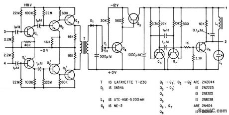
Six-transistor amplifier having high-impedance differential input for commercial eeg or emg electrodes and gain of 10,000 from 5 to 10,000 cps drives modulator Q4-Q5 from decoupling transformer. Modulator makes stimulator (astable mvbr Q6-Q7) apply pulsating voltages to muscles of hand, to make hand open in response to signals picked up by electrodes ovel shoulder muscles, thereby bridging severed arm nerves.-L Vodovnik and W. D. McLeod, Electronic Detours of Broken Nerve paths,Electronics,38:19,p110-116. (View)
View full Circuit Diagram | Comments | Reading(2782)
PRECISION_VOLTAGE_CONTROLLED_OSCILLATOR
Published:2009/7/9 1:50:00 Author:May

This circuit uses a CA3130 BiMOS op amp as a multivibrator and CA3160 BiMOS op amp as a com-parator. The oscillator has a sensitivity of 1 kHz/V, with a tracking error in the order of 0.02%, and a temperature coefficient of 0.01%℃. (View)
View full Circuit Diagram | Comments | Reading(0)
LOE_DISTORTION_VIDEO_BUFFER
Published:2009/7/9 1:49:00 Author:May

This buffer amplifier's overall harmonic distortion is a low 0.01% or less at 3-V rms output into a 500-Ω load with no overall feedback. The LT1010CT offers a 100 V/μs slew rate, a 20 MHz video bandwidth, and 100 mA of output. A pair of JFETs, J1 and J2 are preselected for a nominal match at the bias level of the linearized source-follower input stage, at about 0.5 mA. The sourcebias resistor, R2, of J1 is somewhat larger than R3 so that it can drop a larger voltage and cancel the LT1010CT's offset. J1 and J2 provide an untrimmed dc offset of ± 50 mV or less. Swapping J1 and J2 or trimming the R2 value can give a fmer match.The circuit's overall harmonic distortion is low: 0.01% or less at 3-V rms output into a 500-Ω load with no overall feedback. The circuit's response to a ±5 V, 10 kHz square-wave input, band-limited to 1 μs, has no overshoot. If needed, setting bias resistor RB lower can accommodate even steeper input-signal slopes and drive lower impedance loads with high linearityi The main trade-off for both objectives is more power dissipation. A secondary trade-off is the need for retrimming the source-bias resistor, R2. (View)
View full Circuit Diagram | Comments | Reading(628)
BLOOD_PRESSURE_REGULATOR
Published:2009/7/20 20:46:00 Author:Jessie
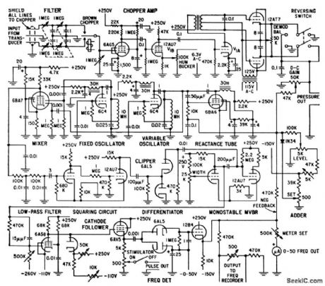
Chopper amplifier delivers d-c voltage to adder that is proportional to mean blood pressure. Potentiometers in adder permit introducing negative voltages corresponding to desired blood pressure level and maximum safe level-R. L. Skinner, D. K. Gehmlich, and F. W. Longson, Blood Pressure and Heart Regulator, Electronics, 32:1, p 38-41. (View)
View full Circuit Diagram | Comments | Reading(899)
CODE_PRACTICE_OSCILLATOR
Published:2009/7/9 1:49:00 Author:May

Capacitor C1 charges through resistor R1, and when the gate level established by potentiometer R2 is high enough, the SCR is triggered. Current flows through the SCR and earphones, discharging C1. The anode voltage and current drop to a low level, so the SCR stops conducting and the cycle is repeated. Resistor R2 lets the gate potential across C1 be adjusted, which charges the frequency or tone. Use a pair of 8-Ω headphones. The telegraph key goes right into the B+ line, 9-V battery. (View)
View full Circuit Diagram | Comments | Reading(0)
Remote_shutdown_regulator+5_voltswith_current_limiting_using_an_ECG915_
Published:2009/7/20 20:46:00 Author:Jessie
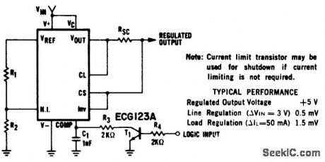
Remote shutdown regulator(+5 volts)with current limiting using an ECG915 or ECG915D.For a ±5% fixed output resistor R1 is 2,15 ohms and R2 is 4.99 ohms.Resistor RSC is 10 ohms(courtesy GTE Sylvania Incorporated). (View)
View full Circuit Diagram | Comments | Reading(772)
PSEUDORANDOM_SIMULATED_FLICKER_SEQUENCER
Published:2009/7/9 1:48:00 Author:May

The pseudorandom sequencer drives a solid-state relay, If you power a low-wattage lamp from the relay, the lamp will appear to flicker like a candle’s flame in the wind; using higher-wattage lamps allows you to simulate the blaze of a fireplace or campfire. You can enhance the effect by using three or more such circuits to power an array of lamps. The circuit comprises an oscillator, IC1, and a 15-stage, pseudorandom sequencer, IC2-4. The sequencer produces a serial bit stream that repeats only every 32767 bits. Feedback from the sequenc-er’s stages 14 and 15 go through IC4D and back to the serial input of IC2. Notice the RC network that feeds IC4C; the network feeds a positive pulse into the sequencer to ensure that it won’t get stuck with all zeros at power-up. The leftover XOR gates IC4A and IC4B further scramble the pattern. The serial stream from IC4B drives a solid-state relay that features zero-voltage switching and can handle loads as high as 1A at 12 to 280 Vac. (View)
View full Circuit Diagram | Comments | Reading(728)
ONE_STAGE_TRANSISTOR_VIDEO_AMPLIFIER
Published:2009/7/20 20:45:00 Author:Jessie

Overcomes Miller capacitance effect that normally causes excessive high-frequency rolloff. Intended for 12-inch and smaller b-w receivers, and provides direct cathode-ray drive. Bandwidth is 2 Mc. Uses MM2260 npn high-voltage silicon epitaxial transistor.-D. L. Wollesen, A Single Stage Video Ampli6er, Motorola Application Note AN-186, Feb. 1966. (View)
View full Circuit Diagram | Comments | Reading(633)
DERIVED_CENTER_CHANNEL_STEREO_SYSTEM
Published:2009/7/9 1:48:00 Author:May


A simple method of deriving a center or third channel without the use of an extra transformer or amplifter. (a) 4-Ω speakers are connected to 8-Ω amplifier taps. 8 and 16-Ω speakers connect to 16-Ω taps. (b) By blending the inputs it is possible to cancel out undesired crosstalk. (View)
View full Circuit Diagram | Comments | Reading(937)
CIRCUIT_TRACER
Published:2009/7/20 20:45:00 Author:Jessie

Continuity tester delivers continuous audio tone when its test terminals are connected by resistance less than about 1 ohm. Circuit under test does not receive more than 3 V or 300 mA, depending on resistance between terminals. Tester ticks softly when switched on but is open-circuited, as reminder that battery drain is then about 0.8 mA. Tester uses sections of Motorola low-power MC3302P quad comparator as measurement comparator, 600-Hz tone oscillator, AF amplifier, and ticker. Pins 3 and 12 of IC are used in power supply.-R. C. Marshall, Continuity Bleeper for Circuit Tracing, Ham Radio, July 1977, p 67-69. (View)
View full Circuit Diagram | Comments | Reading(959)
| Pages:913/2234 At 20901902903904905906907908909910911912913914915916917918919920Under 20 |
Circuit Categories
power supply circuit
Amplifier Circuit
Basic Circuit
LED and Light Circuit
Sensor Circuit
Signal Processing
Electrical Equipment Circuit
Control Circuit
Remote Control Circuit
A/D-D/A Converter Circuit
Audio Circuit
Measuring and Test Circuit
Communication Circuit
Computer-Related Circuit
555 Circuit
Automotive Circuit
Repairing Circuit