Control Circuit
VIDEO_SIGNAL_CLAMP
Published:2009/7/9 2:59:00 Author:May | From:SeekIC

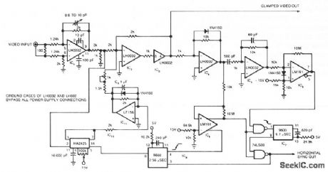
The circuit uses a track-and-hold amplifier in a closed-loop configuration to clamp the back-porch voltage of a standard video waveform to O V. The circuit's outputs include a clamped composite-video signal and a TTL-level horizontal-blanking pulse. Differential input buffer IC1 and the summing amplifier IC2 isolate the input video signal. Clipper IC4 removes the video signal, leaving only the synchronization information. Differentiator IC5 detects the edges of the horizontal blanking pulses and produces pulses that correspond to the leading and trailing edges of the horizontal blanking pulses. IC6 clips these pulses and converts them to a TTL level. IC7 uses these clipped pulses to generate a TTL-level window that, when combined with the horizontal pulse generated by IC8, forms a TTL representation of the original horizontal pulse. This representation is synchronized to the input waveform. IC9 uses the trailing edge of this reconstructed waveform to generate the track pulse for track-and-hold amplifier IC10. IC11 filters 1010's dc output and, after gain adjustment, feeds it back to IC2's summing node.
Reprinted Url Of This Article:
http://www.seekic.com/circuit_diagram/Control_Circuit/VIDEO_SIGNAL_CLAMP.html
Print this Page | Comments | Reading(3)

Article Categories
power supply circuit
Amplifier Circuit
Basic Circuit
LED and Light Circuit
Sensor Circuit
Signal Processing
Electrical Equipment Circuit
Control Circuit
Remote Control Circuit
A/D-D/A Converter Circuit
Audio Circuit
Measuring and Test Circuit
Communication Circuit
Computer-Related Circuit
555 Circuit
Automotive Circuit
Repairing Circuit
Code: