
Circuit Diagram
Index 1154
Battery_backup_regulator
Published:2009/7/24 2:32:00 Author:Jessie

This circuit shows a low-loss way to implement a glitch-free battery backup for a memory or similar circuit. The feedback string is arranged so that one LT1020 does not conduct under line-powered conditions. When the line goes down, the line LT1020 begins to go off, which allows the battery-driven LT1020 to turn on and maintain the load. (View)
View full Circuit Diagram | Comments | Reading(622)
168_GHz_03_W_oscillator_20_V_supply
Published:2009/7/24 2:31:00 Author:Jessie
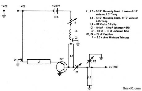
The electrical characteristics for the 2N5108 shown in this circuit are given in Fig.2-20B.Those not familiar with microstrip techniques(for L1,L2,and L3)should read the many Motorola publications, such as AN548A and AN555. (View)
View full Circuit Diagram | Comments | Reading(848)
GENERATES_PREDETERMINED_NUMBER_OF_PULSES
Published:2009/7/24 2:31:00 Author:Jessie
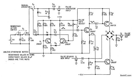
Provides group of pulses with fixed prr, at touch of switch S1, to simulate target returns of various radars. Number of output pulses depends on duration of gate, set by R8.-L. Turf, Simulator Circuit Generates Video or Noise Pulses, Electronics, 39:9, p 78-79. (View)
View full Circuit Diagram | Comments | Reading(585)
V_F_AND_F_V
Published:2009/7/2 3:15:00 Author:May
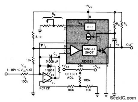
Although basedon Raytheon 4151 IC voltage-to-frequency converter,circuit is readily adapted to other modern V/F converters now costing under $10 each With values shown, input of to-10 VDC provides proportional frequency change from0 to 10 kHz at output. Design equations are given. Article also covers F/V operation of same IC for demodulating FSK data.—T. Gate, IC V/F Converters Readily Handle Other Functions Such as F/V, A/D, EDN Magazine, Jan. 5, 1977, p 82-86. (View)
View full Circuit Diagram | Comments | Reading(861)
CURE_FOR_NOISY_CONTROL
Published:2009/7/2 3:14:00 Author:May
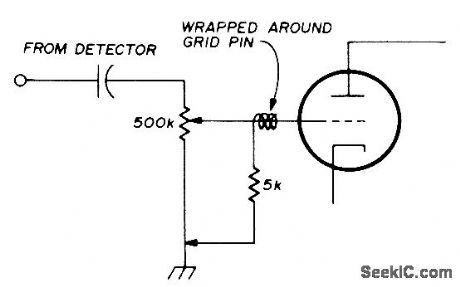
Connecting 5K resistor between grid of first AF stage and ground as shown substantially reduces noise generated by worn volume-control pot in older tube-type communication receiver. Modification can be made from top of chassis by wrapping piece of wire around grid pin of audio tube, bringing wire up alongside tube and out through top of shield. then soldering 5K resistor between wire and chassis.-J. Schroeder,Temporary Fix for Noisy Volume Controls. Ham Radio. Aug. 1974. p 62. (View)
View full Circuit Diagram | Comments | Reading(530)
Offset_linearization_for_type_S_thermocouple
Published:2009/7/24 2:30:00 Author:Jessie

Fig. 13-18 In this circuit, the LT1025 provides cold-junction compensation and the LTC chopper-stabilized amplifier is used for low drift. The type-S thermocouple output slope varies greatly with temperature (at 25℃, the output is 6℃, with an 11μV/℃ slope at 1000℃). This circuit linearizes the output and provides 3℃ accuracy over the indicated output range of 800 to 1200℃. To calibrate, trim R2for a Vout of 1.669 with a Vin, of 0.000 mV. Then, trim R2 for a Vout of 9.998 with a temperature of 1000℃ or for a Vin (+input) of 9.585 mV. (View)
View full Circuit Diagram | Comments | Reading(1522)
BANDPASS_FILTER
Published:2009/7/2 3:14:00 Author:May


The input signal is applied through R3 to the inverting input of the summing amplifier and the output is taken from the first integrator. The summing amplifier will maintain equal voltage at the inverting and non-inverting inputs. Defining 1/R1C1 as ω1 and 1/R2C2 as ω2, this is now a convenient form to look at the center-frequency ω0 and ftlter Q.The frequency response for various values of Q is shown. (View)
View full Circuit Diagram | Comments | Reading(0)
RADIATION_HARDENED,125_A_LINEAR_REGULATOR
Published:2009/7/2 3:10:00 Author:May


Circuit NotesIntended for extreme temperature, radiation-hardened environments, this linear supply is capable of supplying 28 Vdc at 125 A from an acdriven power unit.In operation, power supply output voltage is sensed by the voltage divider consisting of R24 to R28 and fed to one input of a discrete differential amplifier composed of Q13 through Q16. The other input of the amplifier is connected to a radiation-hardened zener diode, D1. Local feedback using R21 and C1 produces gain to phase shift that are independent of individual component parameters, which provides stable operation into the required loads. (View)
View full Circuit Diagram | Comments | Reading(683)
CMOS_monolithic_voltage_converter
Published:2009/7/24 2:30:00 Author:Jessie

Figure 7-57 shows a MAX660 connected to provide either voltage inversion or positive voltage doubling. The conversion efficiency is a typical 88% at 100 mA, with a typical loss of 0.65 V. The typical output impedance is 6.5Ω. The operating current is 120 μA. MAXIM NEW RELEASES DATA Book, 1995, P. 4-73.
(View)
View full Circuit Diagram | Comments | Reading(669)
1_GHz_10-W_amplifier_28-V_supply
Published:2009/7/24 2:30:00 Author:Jessie
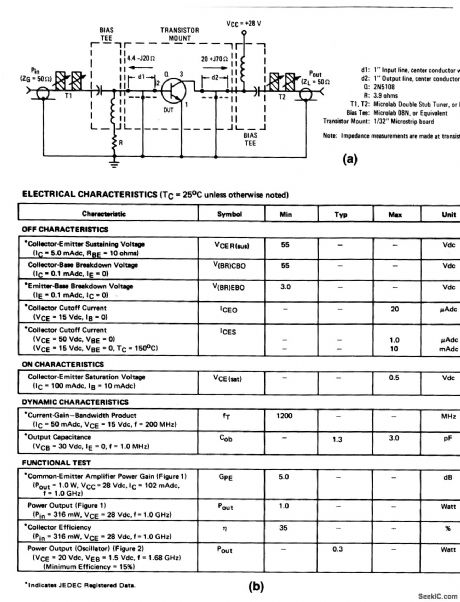
The electrical characteristics for the 2N5108 shown in this circuit are given in Fig 2-20B. (View)
View full Circuit Diagram | Comments | Reading(512)
ACTIVE_BANDPASS_FILTER_f0_1000_Hz
Published:2009/7/2 3:10:00 Author:May

This filter has a bandpass centered around 1kHz, for applications such as bridge amplifiers, null detectors, etc.The circuit uses a μA741 IC and standard 5% tolerance components. (View)
View full Circuit Diagram | Comments | Reading(1435)
PINK_NOISE_FILTER
Published:2009/7/2 3:10:00 Author:May

Used in acoustics for measuring transducer characteristics, absorption-reflection and transmission coefficients of materials, and room parameters such as reverberation time. Offsets falloff of detected noise signal at low frequencies by using filter shown to convert random-noise source from constant energy per hertz (white-noise frequency spectrum) to constant energy per octave (pink-noise response). Filter covers audio range from 10 Hz to 20 kHz, providing -20 dB per decade transmission characteristics with three 741 opamp stages. Frequency characteristic is independent of source and load impedances. Supply voltages can be from ±6 to ±18 V.-R. Mauro, Simple Pink Noise Filter. Audio. March 1977. p 36 and 38. (View)
View full Circuit Diagram | Comments | Reading(1301)
Micropower_regulator_shutdown
Published:2009/7/24 2:29:00 Author:Jessie

This circuit shows a simple way to shut an LT1020 regulator down. In this state, the regulator draws only 40 μA. (View)
View full Circuit Diagram | Comments | Reading(580)
PROGRAMMABLE_BANDPASS_USING_TWIN_T_BRIDGE
Published:2009/7/2 3:08:00 Author:May
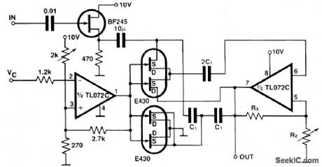
The circuit gives a programmable bandpass where both the cut-over frequency andthe gain,A,are controlled independently.In the twin-T bridge the resistors R and R/2 are replaced by two double FETs,E 430,the channel resistance of the first one in thesenes,the channel resistances of the second one are in parallel as to stimulate the resis-tance R/2. Both these resistors are controlled by Vc which ranges from 0 V to about1 V. The gain of the circuit is set by means of the resistors R2 and R3. (View)
View full Circuit Diagram | Comments | Reading(798)
RADAR_MOVING_TARGET_SIMULATOR
Published:2009/7/24 2:29:00 Author:Jessie
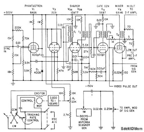
Supplies signal having all characteristics of radar echo, for testing automatic tracking radars under normal and extreme conditions. Phantastron, dual-diode V2, and two-qhase motor serve as variable time-delay.-K. L. Chapman, Moving-Target Simulator Tests Tracking Radars, Electronics, 34:13, p 58-60. (View)
View full Circuit Diagram | Comments | Reading(699)
10_MEGABIT_LINK
Published:2009/7/2 3:08:00 Author:May
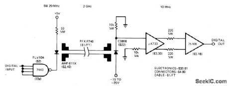
Transmitter and receiver for fiber-optiC data link between teleprinter and microDrocessor utilize wide bandwidth of cable for transmitting data at 10-megabit rate. Receiver input requires C3808 PIN photodiode.-O.E. Marvel and J. C. Freeborn. A Little HandsOn Experience llluminates Fiber-Optic Links,EDN magazine Nov,5,1977,p 71-75. (View)
View full Circuit Diagram | Comments | Reading(1730)
INTRUDER_ALARM
Published:2009/7/2 3:05:00 Author:May

Input is from Mullard RPY86 infrared detector responding to wave-lengths above 6 μm, making it immune to sun-light and backgrounds intermittently illumi-nated by sun. Output signal is produced only when ihcident radiation is changed by movement of intruder in monitored space. Mirrors rather than lenses concentrate incident radia-tion on detector because mirrors do not require high-quality surface finish. Preamp is followed by two amplifier stages, with R10 varying gain of second stage between 10 and 100. Band-width is 0.3-10 Hz. First trigger, having thresh-old of about 1 V, drives second trigger through diode pump to energize alarm relay when in-truder is present.- Ceramic Pyroelectric In-frared Detectors, Mullard, London, 1978, Tech-nical Note 79, TP1664, p 8. (View)
View full Circuit Diagram | Comments | Reading(1862)
50_MHz_40_W_transmitter_125_V_supply
Published:2009/7/24 2:47:00 Author:Jessie
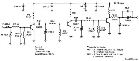
This circuit provides 40 W of output power with 20-mW input power in the 50-MHz band. (View)
View full Circuit Diagram | Comments | Reading(1360)
50_kHz_FM_OPTICAL_TRANSMIlTER
Published:2009/7/2 3:05:00 Author:May
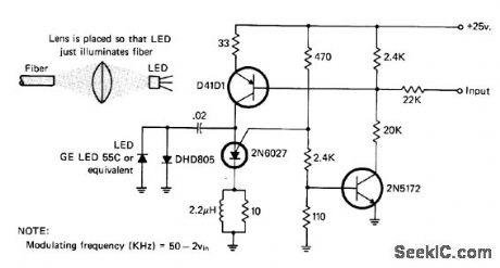
Uses pulse-rate modulation system with center frequency of 50 kHz. Audio fed into transmitter varies pulse rate, for driving LED coupled to optical fiber. Phototransistor at other end of fiber receives and demodulates light signal for reconstruction of audio.-I. Math, Math's Notes, Ca July 1977, p 67-68 and 90. (View)
View full Circuit Diagram | Comments | Reading(1589)
1_10_100_KILOBIT_FIBER_OPTIC_RECEIVER
Published:2009/7/2 3:02:00 Author:May
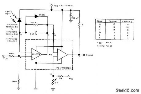
Choice of input device determines operating speed of receiver. MC3405 contains two opamps and two comparators, permitting use as two-channel receiver. Table gives pin connections foi each channeL- Basic Experimental Fiber Optic Systems, Motorola, Phoenix, AZ, 1978. (View)
View full Circuit Diagram | Comments | Reading(1574)
| Pages:1154/2234 At 2011411142114311441145114611471148114911501151115211531154115511561157115811591160Under 20 |
Circuit Categories
power supply circuit
Amplifier Circuit
Basic Circuit
LED and Light Circuit
Sensor Circuit
Signal Processing
Electrical Equipment Circuit
Control Circuit
Remote Control Circuit
A/D-D/A Converter Circuit
Audio Circuit
Measuring and Test Circuit
Communication Circuit
Computer-Related Circuit
555 Circuit
Automotive Circuit
Repairing Circuit