
Circuit Diagram
Index 1142
12_V_high_efficiency_controller_non_boot_stmpped
Published:2009/7/24 2:13:00 Author:Jessie

Figure 7-52 shows the MAX1771 connected to provide 12-V output at 0.5 A, with a 5-V input. See Fig. 7-51 for component suppliers. This non-boot-strapped version of the Fig. 7-50 controller requires less supply current, but with the full 5-V input. Use the Fig. 7-50 controller for input less than 5 V. Maxnvt NEW RELEASES DATA BOOK, 1995, P. 4-20.
(View)
View full Circuit Diagram | Comments | Reading(665)
SPECTRUM_INVARIANT_RANDOM_FUNCTION_GENERATOR
Published:2009/7/24 2:13:00 Author:Jessie
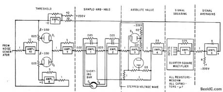
Operational amplifiers of analog computer produce periodically slopped waves by clipping and sampling raw noise signal. Feedback maintains desired power density spectrum.-N. D. Diamantides and C. E. McCray, Generating Random Forcing Functions for Control-Systems Simulation, Electronics, 34:33, p 60-63. (View)
View full Circuit Diagram | Comments | Reading(491)
Temperature_to_digital_converter_parallel_output
Published:2009/7/24 2:09:00 Author:Jessie

Fig. 13-7 This circuit converts temperature (from 0 to 128°F) to a parallel data word (8 bits when appropriate read, write, chip-select signals are received from the system). The circuit can be interfaced with a standard microprocessor data bus, and it provides an interrupt signal to the microprocessor. The scales are adjusted by the 1-kΩ pot so that all 8 bits are at digital1 when the temperature is +128°F. In practice, the VREF/2 pin of the ADC0804 is set to 0.64V. National Semiconductor Linear Applications Handbook. 1991 p 1077. (View)
View full Circuit Diagram | Comments | Reading(567)
RE_IF_amplifiers
Published:2009/7/24 2:08:00 Author:Jessie

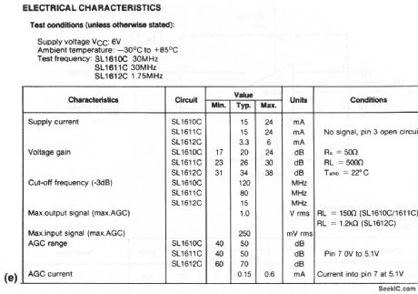
The SL1610, SL1611, and SL1612 shown in these circuits are RF voltage amplifiers with AGC provisions. The voltage gains are 10, 20, and 50, respectively, and the upper frequency response varies from 15 to 120 MHz, according to the type. Figure 2-8A shows three SL1612Cs connected as an IF amplifier(with AGC). Figure 2-8B shows any of the three ICs connected as an RF amplifier (without AGC). Figures 2-8C and 2-8D show the AGC characteristics and gain versus frequency, respectively, for the three ICs. Electrical characteristics are shown in Fig. 2-8E. (View)
View full Circuit Diagram | Comments | Reading(763)
MEASURING_SPOT_WELDING_CURRENT
Published:2009/7/24 2:08:00 Author:Jessie

Toroid placed around one of welder electrodes develops voltage that is function of rate of change of magnetic flux produced by alternating current lowing through weld. Peak-reading a-c electronic voltmeter is used to measure resulting voltage across toroid. Selector switch positions are: 1-no signal input; 2-0 to 15,000 amp; 3-0 to 30,000 amp; 4-calibration.-J. Markus, Handbook of Electronic Control Circuits, McGraw-Hill,1959, p 326. (View)
View full Circuit Diagram | Comments | Reading(1019)
Temperature_to_digital_converter_serial_output
Published:2009/7/24 2:07:00 Author:Jessie

Fig. 13-6 This circuit converts temperature (from 0 to 128°F) to a serial data word (8 bits when appropriate clock and enable signals are received from the system). The scales are adjusted by the 10-kΩ pot so that all 8 bits are at digital 1 when the temperature is + 128°F, In practice, the VREF pin of the LM385 is set to 1.28 V. National Semiconductor, Linear Applications Handbook 1991 p 1076. (View)
View full Circuit Diagram | Comments | Reading(560)
01_1000_CPS_DECADE_SWITCHING_TWO_PHASE_OSCILLATOR
Published:2009/7/24 2:07:00 Author:Jessie
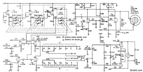
Simultaneous outputs at 90 deg phase difference have constant amplitudes over entire range. Direct coupling between stages avoids phase error.-Y. P. Yu, Two-Phase Oscillator Covers 0.1 to 1,000-CPS, Electronics, 36:40, p 27-29. (View)
View full Circuit Diagram | Comments | Reading(542)
PRESET_VOLTAGE_LIMIT_MONITOR
Published:2009/7/24 2:07:00 Author:Jessie


Used In automatic testing equipment to determine if voltage is within required go-band, Uses complementary transistors In blocking oscillator circuits with high Input impedance and with low hysteresis at switching limits.-L. Smith, High-Impedance Voltage Monitoring Circuit, EEE, 12:4,p 65. (View)
View full Circuit Diagram | Comments | Reading(716)
COMBINED_R_F_AND_A_F_OSCILLATOR
Published:2009/7/24 2:06:00 Author:Jessie
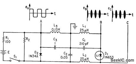
Used for checking am receivers. Generates r-f at 0.6 Mc, determined by L1-C1, and relaxation-type audio output of 400 cps at A.-W. H. Ko, Tunnel-Diode Oscillator Delivers R-F and Audio, Electronics, 35:41, p 56. (View)
View full Circuit Diagram | Comments | Reading(488)
Remote_temperature_sensor_output_referenced_to_ground
Published:2009/7/24 2:06:00 Author:Jessie

Fig. 13-5 This circuit is similar to that of Fig. 13-4, except that is not grounded and the output is referred to ground (slightly above ground). National Semicondutor Linear Applications Handbook 1991 p 1076. (View)
View full Circuit Diagram | Comments | Reading(466)
Programmable_DIE_DCE_transceiver
Published:2009/7/24 2:06:00 Author:Jessie
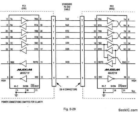
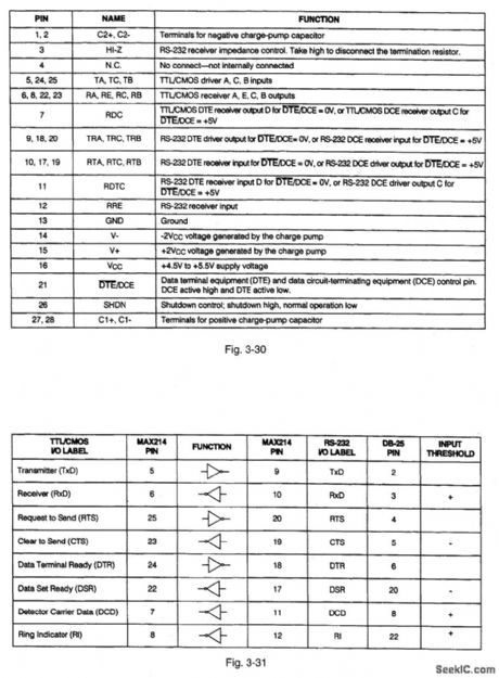
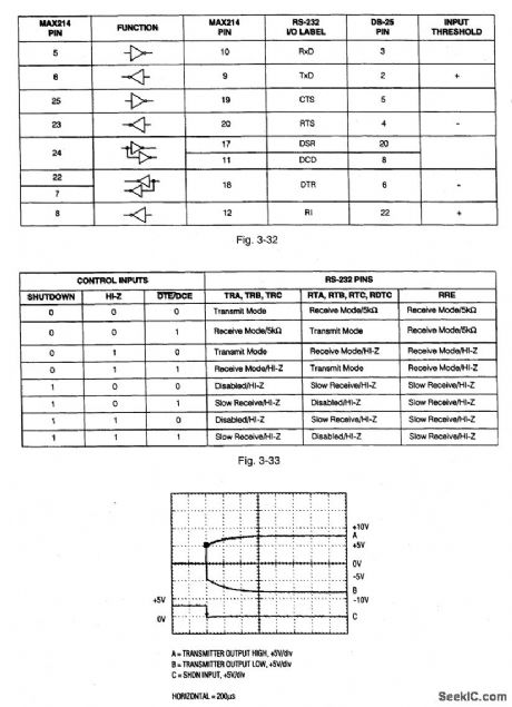
Figure 3-29 shows a typical application circuit (where two PCs have both DTE and DCE operation) for the MAX214. Figures 3-30, 3-31, 3-32, and 3-33 show the pin descriptions. Figure 3-34 shows the scope display for transmitter outputs when exiting shutdown. This IC provides a software-configurable DTE (data terminal equipment) or DCE (data circuit-terminating equipment) port RS232 interface. Either DTE or DCE is selected using the DTE/DCE pin (21). This IC eliminates the need to swap cables when switching between DTE and DCE configurations. MAXIM NEW RELEASES DATA BOOK, 1995, P, 2-69, 2-70, 2-72, 2-73, 2-74.
(View)
View full Circuit Diagram | Comments | Reading(682)
FET_WIEN_BRIDGE_OSCILLATOR
Published:2009/7/24 2:06:00 Author:Jessie
Used where good amplitude stability is required for wide frequency variations. Two-stage R.C coupled doss A amplifier has positive feedback loop that causes oscillation, and negative feed.buck loop that stabilizes amplitude of oscillation. Frequency ranges are 20 to 200 cps, 200 cps to 2 kc, 2 to 20 kc, and 4 to 40 kc.-L. J. Sevin, Jr., Field-Effect Transistors, McGraw-Hill, N.Y., 1965, p 113, (View)
View full Circuit Diagram | Comments | Reading(1006)
A_C_OPERATED_PEAK_READING_VOITMETER
Published:2009/7/24 2:06:00 Author:Jessie

Uses tunnel diode and silicon controlled switch to give d-c output proportional to positive peak of input signal- Transistor Manual, Seventh Edition, General Electric Co., 1964, p 371. (View)
View full Circuit Diagram | Comments | Reading(509)
Single_cell_flyback_regulator
Published:2009/7/24 2:05:00 Author:Jessie

This 1.5-V powered regulator provides a 5-V output, at currents up to 2200 μA. As shown by the graph of Fig. 8-14B, efficiency is greatest at currents above 1500 μA, and drops off at lower currents (because of fixed losses in the regulator). (View)
View full Circuit Diagram | Comments | Reading(564)
SPECTRUM_ANALYZER_FILTER
Published:2009/7/24 2:05:00 Author:Jessie
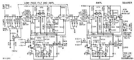
Designed to study dynamic data recorded as frequency-modulated signals on magnetic tape. Filter circuit values give 1, 2, and 4-cps bandwidth in analyzer. Thermocouple in squarer has time constant of 1 sec so output is filtered as well as squared. Outputs of thermocouples are in series to provide summing. D-c amplifiers prevent loading of filters,-T. B. Fryer, Frequency Analyzer Uses Two Reference signals, Electronics, 32:18, p 56-57. (View)
View full Circuit Diagram | Comments | Reading(800)
FREQUENCY_TRACKING_BANDPASS
Published:2009/7/2 8:49:00 Author:May

High-Q active bandpass filter automatically tracks input signal frequency over 10:1 range in presence of noise.When signal goes outside tracking range, circuit sweeps between low- and high-frequency limits until suitable signal reappears. Circuit is basically voltage-controlled bandpass filter using Optical Electronics 3704 active filter with 5898 analog multipliers. 9813 opamp connected as Schmitt trigger is main element of scanning circuit. Frequency range is 160 to 1600 Hz, and FM bandwidth of error-voltage output is 20 Hz.- Frequency Tracking Active Filter, Optical Electronics, Tucson, AZ, Application Tip 10270. (View)
View full Circuit Diagram | Comments | Reading(1050)
1_kHz_MULTIPLE_FEEDBACK_BANDPASS
Published:2009/7/2 8:47:00 Author:May

Single 741 or equivalent opamp is suitable for applications where bandwidth is less than 100%.Gain is fixed at -2Q2, where Q is reciprocal of damping d and ranges from less than 1 to above 100. Q is changed by varying ratio of input and feedback resistors while keeping their product constant. For Q of 3, feedback resistor should be 36 times value of input resistor.-D. Lancaster, Active-Filter Cookbook, Howard W. Sams, Indianapolis, IN, 1975, p 150-154. (View)
View full Circuit Diagram | Comments | Reading(810)
1_Hz_STATE_VARIABLE_FILTER
Published:2009/7/2 8:46:00 Author:May


Universal filter has simultaneous low-pass, bandpass, high-pass, and notch outputs all with cutoff frequency of 1 Hz. To scale circuit up to 1-kHz cutoff, replace 10-megohm resistors with 10K.-D.Lancaster, CMOS Cookbook, Howard W.Sams, Indianapolis, IN, 1977, p 343-344. (View)
View full Circuit Diagram | Comments | Reading(840)
20_kHz_BANDPASS
Published:2009/7/2 8:44:00 Author:May

Provides bandwidth of 2000 Hz and midband gain of 1 for applications requiring narrow-bandwidth bandpass active filter. Design procedure is given.- Audio Handbook, National Semiconductor, Santa Clara, CA, 1977, p 2-52-2-53. (View)
View full Circuit Diagram | Comments | Reading(954)
1__kHz_THREE_FUNCTION
Published:2009/7/2 8:42:00 Author:May

Three-function fixed-frequency active filter uses three sections of RCA CA3401E, Motorola MC33OlP, or National CA3401E quad opamp. Circuit uses highvalue series resistors for noninverting inputs to limit bias current to between 10 and 100,μA.-P. A. Lovelock, Discrete Operational Amplifier Active Filters, Ham Radio, Feb. 1978, p 70-73. (View)
View full Circuit Diagram | Comments | Reading(516)
| Pages:1142/2234 At 2011411142114311441145114611471148114911501151115211531154115511561157115811591160Under 20 |
Circuit Categories
power supply circuit
Amplifier Circuit
Basic Circuit
LED and Light Circuit
Sensor Circuit
Signal Processing
Electrical Equipment Circuit
Control Circuit
Remote Control Circuit
A/D-D/A Converter Circuit
Audio Circuit
Measuring and Test Circuit
Communication Circuit
Computer-Related Circuit
555 Circuit
Automotive Circuit
Repairing Circuit