
Circuit Diagram
Index 1144
TWO_STAGE_POSTAMPLIFIER
Published:2009/7/2 7:52:00 Author:May

Connections shown for CA36OOE CMOS transistor-pair array give total open-loop gain of about 160 dB for system. Open-loop slew rate is about 65 V/μs.- Linear Integrated Circuits and MOS/FET's. RCA Solid State Division, Somerville, NJ, 1977, p278-279. (View)
View full Circuit Diagram | Comments | Reading(597)
COHO
Published:2009/7/24 2:12:00 Author:Jessie
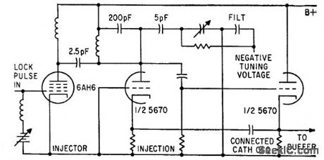
Connected-cathode coherent oscillator has compromise between good short-term frequency stability and good locking ability, as required for measuring pulse-to-pulse phase variation in pulsed r-f systems.-R. H. Holman and R. B. Shields, Measuring Frequency Stability of Pulsed Signals, Electronics, 34:16, p 61-65. (View)
View full Circuit Diagram | Comments | Reading(720)
QUADRATURE__OSCILLATOR
Published:2009/7/2 7:45:00 Author:May

Addition of diode limiter and positive-feedback resistor to UAF41 universal active filtrer gives precision quadrature oseillator.-Y. J. Wong, Design a Low Cost, Low-Distortion, Precision Sine-Wave Oscillator,EDN Magazzine,Sept20, 1978,p 107-113. (View)
View full Circuit Diagram | Comments | Reading(931)
Remote_temperature_to_frequency_converter
Published:2009/7/24 2:12:00 Author:Jessie

Fig. 13-8 This circuit converts temperature (from +3°to +300°F) to a corresponding frequency (30 to 3000 Hz). The output is isolated by a 4N28. The circuit can be used to send temperature information across long transmission lines because the 4N28 output voltage can be selected, as required. The scales are adjusted by the total value of RS (12-kΩ fixed and 5-kΩ variable). In practice, when RS is set to about 14.2 kΩ, the output is 10 Hz/°F. (View)
View full Circuit Diagram | Comments | Reading(1134)
MODULATOR_WITH_FEEDBACK
Published:2009/7/24 2:11:00 Author:Jessie
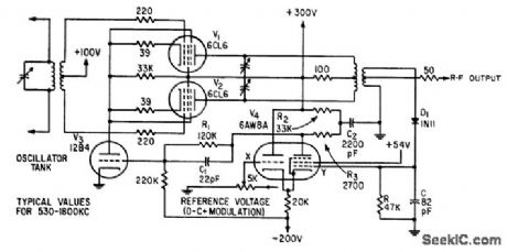
Automatic amplitude stabilization of r-f test signals, within 1 db over 1,300 to 1 frequency range, is achieved by demodulating r-f output with D1 and feeding demodulated voltage back to grid Y of differential amplifier V4. Permits rapid and accurate response measurements over wide range without resetting signal level to input of device under lest.-A. Fong, Feedback Stabilizes Signal Generator, Electronics, 33:29, p 71-73. (View)
View full Circuit Diagram | Comments | Reading(530)
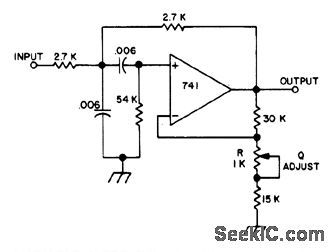
VARIABLE_DEAD_BAND_RESPONSE
Published:2009/7/2 7:44:00 Author:May
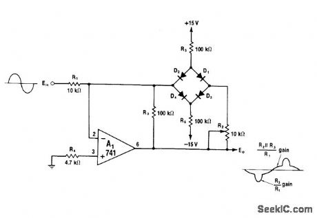
Diode bridge in feedback loop of opamp provides controlled amount of dead-band response. As value of R2 is increased from 0 ohms, voltage developed across R2. serves to raise dead-band level at which bridge opens and circuit amplifies with normal gain of R3/R1. Below dead-band level. bridge is blocked and circuit gain is equal to parallel combination of R2 and R3 divided by R1. Use matched diodes such as CA3O19 for peaks below ±7 V; for higher peaks,.use 1N914s.-W.G. Jung, IC Op-Amp Cookbook, Howard W.Sams. Indianapolis IN.1974. p 207. (View)
View full Circuit Diagram | Comments | Reading(1237)
Single_cell_temperature_compensated_crystal_clock
Published:2009/7/24 2:11:00 Author:Jessie

This 1.5-V oscillator provides a temperature-compensated output without the use of a current-consuming oven. Figure 8-15B shows the compensated-versus-uncompensated oscillator drift. Current consumption is 850 μA or less. The varactor diode tunes the oscillator frequency as the dc bias varies. An ambient-temperature-dependent bias is generated by the remaining circuitry. (View)
View full Circuit Diagram | Comments | Reading(876)
CONTROLLABLE_12_dB_PER_OCTAVE_ROLLOFF
Published:2009/7/2 7:43:00 Author:May
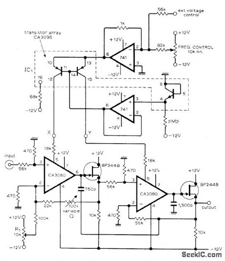
Frequency at which rolloff starts can be set in range between 15 and 15,000 Hz by extemal voltage or current. If only manual control of frequency is required, short points X and Y and conned them to wiper of 10,000-ohm logarithmic potentiometer that is positioned between -12 V and ground.-T.Orr, Voltage/Current Controlled Filter, Wireless World,Nov.1976, p 63. (View)
View full Circuit Diagram | Comments | Reading(559)
100_Hz_HIGH_PASS
Published:2009/7/2 7:41:00 Author:May
Metallized polycarbonate capacitor are required for good temperature stability in high-pass active filter using voltage-follower opamp. Cutoff frequency is 100 Hz.- The Linear and Interface Circuits Data Book for Design Engineers, Texas instruments, Dallas, TX, 1973, p 4-39. (View)
View full Circuit Diagram | Comments | Reading(488)
SPOT_WELDING__TIMER
Published:2009/7/24 2:10:00 Author:Jessie

Five-thyratron sequence timer for resistance-type spot welder meets auto industry requirements for efficiency and reliability.-J. Markus and V. Zeluff, Handbook of Industrial Electronic Control Circuits, McGraw-Hill, New York,1956,p 343. (View)
View full Circuit Diagram | Comments | Reading(2360)
ACTIVE_AF_FOR_SSB_AND_CW
Published:2009/7/2 7:40:00 Author:May
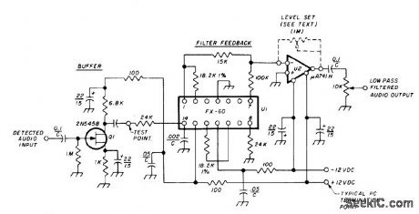
Uses Kinetic Technology FX-60 IC (culled from FS-60, FS-65, and FS-61 production by manufacturer) as 2.5-kHz tunable detected-audio low-pass filter for SSB. Provides inexpensive hybrid active filter using multiloop negative feedback for low-pass transfer functions. External resistors tune filter frequency and give choice of Q. High-impedance buffer Ql provides nominal gain while isolating filter from previous receiver stages.Opamp U2 boosts overall gain.-M. A. Chapman, Audio Filters for Improving SSB and CW Reception,Ham Radio,Nov.1976,p 18-23. (View)
View full Circuit Diagram | Comments | Reading(2906)
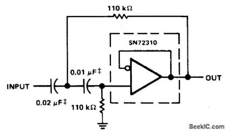
60_Hz_ADJUSTABLE_Q_NOTCH
Published:2009/7/2 7:37:00 Author:May
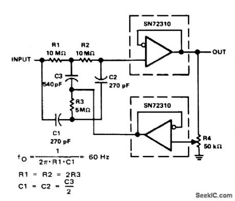
Connection shown for two SN72310 voltage-follower opamps provides attenuation of 60-Hz power-line frequency. Setting of R4 determines a of filter.- The Linear and Intelface Circuits Data Book for Design Engineers, Texas Instruments, Dallas, TX, 1973, p 4-39. (View)
View full Circuit Diagram | Comments | Reading(440)
NARROW_BANDPASS_FOR_SPEECH
Published:2009/7/2 7:36:00 Author:May

Simple audio filter provides about 20-dB gain at bandwidth of 80 Hz Bandwidth can be narrowed tolimits of unintelligibility by adjusting 10K pot.Input is plugged into phone jack of receiver, and headphones are connected to output. Transistors are SK3004 or equivalent.-Circuits, 73 Magazine, Jan.1974 p 125. (View)
View full Circuit Diagram | Comments | Reading(869)
Wideband_AGC_amplifier
Published:2009/7/24 2:10:00 Author:Jessie
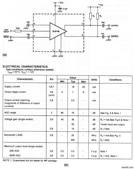

The SL640 shown in this circuit is a broadband amplifier, providing over 15 dB of linear gain into 50Ω at 400 MHz.Figure 2-9B shows the electrical characteristics. Figures 2-9C, 2-9D,and 2-9E show AGC characteristics, differential output, and single-ended voltage gain, respectively. (View)
View full Circuit Diagram | Comments | Reading(0)
VARIABLE_Q_FOR_CW
Published:2009/7/2 7:35:00 Author:May
Fixed-frequency active filter gives slowly rising and falling keyed waveform with good slope considering narrowness of bandwidth, which is 75 Hz at 3 dB down. Adjusting Q with 1K pot changes bandwidth.-A.F. Stahler, An Experimental Comparison of CW Audio Filters, 73 Magazine, July 1973, p 65-70. (View)
View full Circuit Diagram | Comments | Reading(516)
LINEAR_FREQUENCY_SWEEP_GENERATOR
Published:2009/7/24 2:10:00 Author:Jessie

Frequency is swept from 400 to 600 kc electronically by using reverse-biased pn junction diode C as variable capacitor in oscillator V5. Frequency markers are provided. Output is amplified and filtered to give 6 w into 150 ohms with high purity of wave form.-M. M. Brady, Oscillator Design Using Voltage-Variable Capacitors, Electronics, 32:34, p 38-40. (View)
View full Circuit Diagram | Comments | Reading(1292)
TWO_STAGE_CW
Published:2009/7/2 7:33:00 Author:May
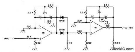
Uses diode threshold detector between stages to prevent weak undesired signals from passing through until CW signal of desired frequency is present, so as to provide quiet tuning between signals. Bandwidth of filter is sharp (16 Hz), and keyed waveform is good. Gain is near unity, and frequency and Q are both fixed.-A. F. Stahler, An Experimental Comparison of CW Audio Filters, 73 Magazine, JuIy 1973, p 65-70. (View)
View full Circuit Diagram | Comments | Reading(515)
TIMER_FOR_RESISTANCE_WELDING_GUN
Published:2009/7/24 2:10:00 Author:Jessie

Provides exact timimg control for squeeze, weld, and hold, us well as fast repeat recycling, by control of thyratrons. Can be operated anywhere from single-shot to over 600 spots per minute. Timer is designed for fail-safe peration.-J. Markus, Handbook of Electronic Control Circuits, McGraw-Hill, New York, 1959, p 322. (View)
View full Circuit Diagram | Comments | Reading(739)
DIGITAL_CONTROL_T0_100_kHz
Published:2009/7/2 7:30:00 Author:May

Schmitt trig-ger function of CD4093B IC gives oscillator op-eration over four decades of frequency without changing C. Basic frequency value is equal to kl RC, with k equal to 1.3 up to about 5 kHz and decreasing gradually to 1.0 at 100 kHz. Use of CD4016 quad transmission gate permits remote switching in of additional resistors to provide direct digital control of frequency. Arrangement shown gives choice of five unrelated frequen-cies, but binary selection of binary-weighted re-sistors witl give choice of 16 unrelated frequen-cies.-R. Tenny, CMOS Oscillator Features Digital Frequency Control, EDNMagazine, June 5, 1976, p 114 and 116. (View)
View full Circuit Diagram | Comments | Reading(659)
8O0_kHz_OSCILLATOR
Published:2009/7/2 7:28:00 Author:May

National LM3909 IC operating from single 1.5-V cell is used with standard AM radio ferrite antenna coil having tap 4070 of turns from one end, with standard 365 pF tuning capacitor across coil. Developed for demonstrating versatility of this low-voltage IC.- Linear Applications, Vo1. 2. National Semiconductor, Santa Clara, CA, 1976, AN-154, p8. (View)
View full Circuit Diagram | Comments | Reading(658)
| Pages:1144/2234 At 2011411142114311441145114611471148114911501151115211531154115511561157115811591160Under 20 |
Circuit Categories
power supply circuit
Amplifier Circuit
Basic Circuit
LED and Light Circuit
Sensor Circuit
Signal Processing
Electrical Equipment Circuit
Control Circuit
Remote Control Circuit
A/D-D/A Converter Circuit
Audio Circuit
Measuring and Test Circuit
Communication Circuit
Computer-Related Circuit
555 Circuit
Automotive Circuit
Repairing Circuit