About SeekIC | Services | Payment | Advertisements service | Contact Us | Links
© 2008-2012 SeekIC.com Corp.All Rights Reserved.

Published:2009/7/2 9:09:00 Author:May
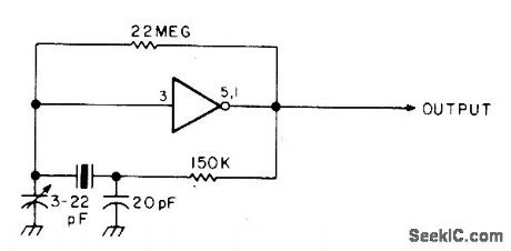
Simple mono multivibrator circuit using MC14007 or CD4007 operates in frequency range from 10 kHz up to top limit of about 10MHz, with exact frequency depending on values used for R and C. Pin 7 of IC is VSS and pin 14 is VDD. Pins 5 and 1 must be connected together for proper operation.-W. J. Prudhomme, CMOS Oscillators, 73 Magazine, July 1977, p 60-63. (View)
View full Circuit Diagram | Comments | Reading(961)
Published:2009/7/24 2:18:00 Author:Jessie
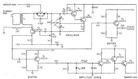
Tank circuit L1-C1-C2-C3 sweeps frequency of transistor Clapp oscillator over range of 5 to 15 Mc when current through bias winding of L1 is varied from zero to 800 ma. Collector voltage is servoed to maintain con slant output amplitude.-R. E. Daniels and A. D. Cook, Advanced Clapp Oscillator Features 3-to-1 Dynamic Range, Electronics, 36:8, p 60-61. (View)
View full Circuit Diagram | Comments | Reading(1107)
Published:2009/7/2 9:08:00 Author:May

Adding crystal in frequency-determining circuit improves frequency stabrlity of UJT relaxation oscillator. With charging capacitor replaced by 100-kHz quartz crystal, measured output frequency was 99.925 kHz. -R. D. Clement and R. L. Starliper, Crystal-Controlled Relaxation Oscillator, EDN|EEE Magazine, Oct. 15, 1971, p 62 and 64. (View)
View full Circuit Diagram | Comments | Reading(946)
Published:2009/7/24 2:18:00 Author:Jessie

This circuit operates from a 6- or 9-V battery and provides 5-V output at 20 mA. Figure 8-18B shows output current and efficiency for both 6- and 9-V operation. (View)
View full Circuit Diagram | Comments | Reading(623)
Published:2009/7/2 9:07:00 Author:May
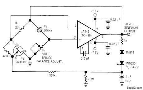
Crystal osyillator using Meacham bridge requires no transformers for producing low-distortion sine-wave output. Quartz crystal should be cut for operation in series-resonant mode. With minor modifications, same circuit can be used for 100- and 200-kHz crystals. By adding single-transistor stage, oscillator can be used as clock generator for TTL circuits.-K. J. Peter, Stable Low-Distortion Bridge Oscillator, EDN|EEE Magazine, Nov. 15, 1971, p 50-51. (View)
View full Circuit Diagram | Comments | Reading(1474)
Published:2009/7/2 9:05:00 Author:May

Circuit is ideal for low-frequency crystal oscillators because JFET circuit loading does not vary with temperature. Output frequency is determined by threshold used.- FET Databook, National Semiconductor, Santa Clara, CA, 1977, p 6-26-6-36. (View)
View full Circuit Diagram | Comments | Reading(1017)
Published:2009/7/24 2:18:00 Author:Jessie

Flip-flop thyratron circuit makes pairs of ignitrons share load alternately, to prevent overloading of tubes when welder is used for heavier weld or for longer lime than originally intended.-J. Markus and V. Zeluff, Handbook of Industrial Electronic Control Circuits, McGraw-Hill, New York, 1956, p 342. (View)
View full Circuit Diagram | Comments | Reading(810)
Published:2009/7/2 9:05:00 Author:May

Tuning two-gang 365-pF variable capacitor through its range provides frequency change up to 5 kHz in output of 8-MHz crystal oscillator. L1 is 16-24 μH Miller 4507, and L2 is 40 turns No.36 tapped at 13 turns, on 1/4-inch slug-tuned form.-Circuits, 73 Magazine, Jan. 1974, p 128. (View)
View full Circuit Diagram | Comments | Reading(1062)
Published:2009/7/24 2:18:00 Author:Jessie

Fig. 13-13 This circuit uses an LM604 mux/amplifier to monitor several temperatures periodically, rather than continuously. Each channel is multiplexed to the output, according to the AB channel select. The CD4060 ripple binary counter has an on-board oscillator for continuous updating of the channel selects. National Semiconductor, Linear Applications Handbook 1991 p 1080. (View)
View full Circuit Diagram | Comments | Reading(648)
Published:2009/7/2 9:04:00 Author:May

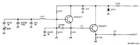
Used in 1.8-2 MHz communication receiver having wide dynamic range. Oscillator has good stability, with circuit noise at least 90 dB below fundamental output. Amplifier Q14 provides required +7 dBm for in jection into balanced mixer of receiver. Two-part article gives all other circuits of receiver.-D. DeMaw, His Eminence-the Receiver, QST, Part 1-June 1976, p 27-30 (Part 2-July 1976, p 14-17). (View)
View full Circuit Diagram | Comments | Reading(878)
Published:2009/7/24 2:18:00 Author:Jessie

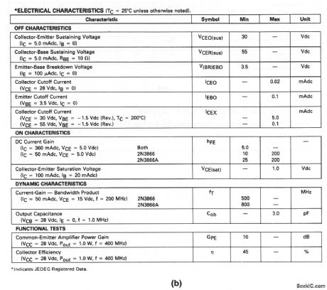
The electrical characteristics for the 2N3866 shown in this circuit are given in Fig. 2-13B. (View)
View full Circuit Diagram | Comments | Reading(1707)
Published:2009/7/2 9:03:00 Author:May
Simple and stable circuit using PNP transistors has tuning range of about 250 kHz in any segment of 5-9 MHz range, depending on how oscillator coil is set. Wind coil on ceramic form or use air-wound coil. Capacitors marked M should be mica for stability. Tuning capacitor is 365 pF,from AM radio, 400/N750 temperature-compensating capacitor can be replaced by 400-pF mica unless VFO is used in mobile application.-An Accessory VFO-the Easy Way, 73 Magazine, Aug. 1975, p 103 and 106-108. (View)
View full Circuit Diagram | Comments | Reading(703)
Published:2009/7/2 9:02:00 Author:May

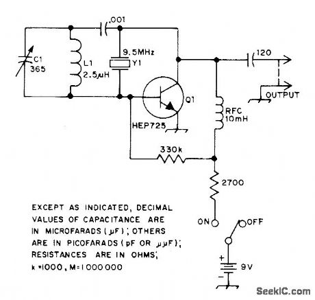
Maximum frequency shift is almost 10 kHz at 5 MHz. Use crystal made especially for variable operation. Frequency stability is good even at extremes of shift. Use 5-20 μH for L1 with crystals from 6-15 MHz, and 20-50 μH for 3-6 MHz. Q1 is 2N3563, 2N3564, 2N5770, BC107, BC547, BF115, BF180, SE1010, or equivalent.-R. Harrison, Sulvey of Crystal Oscillators, Ham Radio, March 1976, p 10-22. (View)
View full Circuit Diagram | Comments | Reading(2265)
Published:2009/7/24 2:14:00 Author:Jessie

Pig. 13-10 The indoor and outdoor LM34 outputs are multiplexed through a CD4066 quad bilateral switch and then displayed (one at a time) on a DVM such as Texmate's PM-35X. Temperature range is -50° to +300°F. The LMC555 timer is run as an astable MV at 0.2 Hz so that each temperature is displayed for about 2.5 s. The RC filters at the LM34 outputs compensate for the capacitive loading of the cable. Notice that R1 must be selected to provide 50μA with the available -U supply (see Fig. 13-3). An LMC7660 can be used to provide -VS. National Semiconductor, Linear Applications Handbook, 1991, p. 1078. (View)
View full Circuit Diagram | Comments | Reading(956)
Published:2009/7/24 2:14:00 Author:Jessie
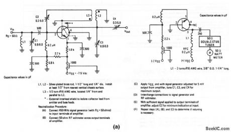
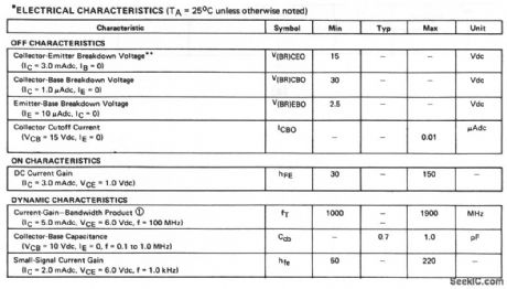
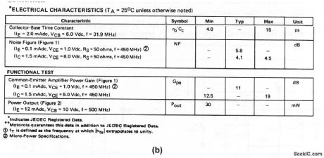
The electrical characteristics for the 2N2857 shown in this circuit are given in Fig.2-11B (View)
View full Circuit Diagram | Comments | Reading(537)
Published:2009/7/2 9:00:00 Author:May
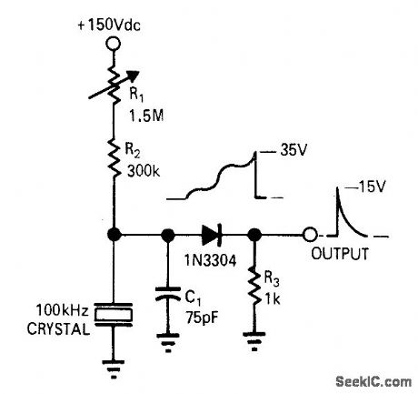
Crys tal-controlled relaxation oscillator uses 1N3304 four-layer diode as active element, R1 adjusts RC time constantso oscillator locks at fundamental frequency of crystal or at half this frequency.-R. D. Clement and R. L. Starliper, Crystal-Controlled Relaxation Oscillator, EDN|EEE Magazine, Oct. 15, 1971, p 62 and 64. (View)
View full Circuit Diagram | Comments | Reading(894)
Published:2009/7/2 8:59:00 Author:May
Adding parallel resonant circuit across crystal, tuned slightly above crystal frequency, makes oscillator frequency increase. Some plated crystals will work better than others in this circuit; third-overtone types operating on their fundamental generally give best results. Article covers theory of operation.-L. Lisle, The Tunable Crystal Oscillator, QST, Oct. 1973, p 30-32. (View)
View full Circuit Diagram | Comments | Reading(920)
Published:2009/7/2 8:52:00 Author:May

Uses opamp in circuit having essentially zero output impedance, making additional buffer amplifier unnecessary. Article gives design theory and covers many other types of notch filters.-Y.Nezer, Active Notch Filters, Wireless World, July 1975, p 307-311. (View)
View full Circuit Diagram | Comments | Reading(1735)
Published:2009/7/24 2:14:00 Author:Jessie

This 1.5-V powered sample-hold circuit has an acquisition time of 125 μS to 0.1% with a droop rate of 10 μV/ms. Current consumption is less than 700 μA. (View)
View full Circuit Diagram | Comments | Reading(696)
Published:2009/7/24 2:14:00 Author:Jessie
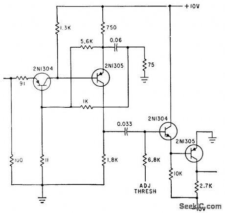
Used in programmed digital signal generator in which plug-in magnets set up program Input, nominally 100 mV, is amplified and clipped before it is gated with strobing pulse.-W. D. Woo, Novel Digital Signal Generator Uses Magnetic-Core Pegboard, Electronics, 35:27, p 46-49. (View)
View full Circuit Diagram | Comments | Reading(556)
| Pages:1141/2234 At 2011411142114311441145114611471148114911501151115211531154115511561157115811591160Under 20 |
Response in 12 hours
© 2008-2012 SeekIC.com Corp.All Rights Reserved.