Basic Circuit
VARIABLE_DEAD_BAND_RESPONSE
Published:2009/7/2 7:44:00 Author:May | From:SeekIC

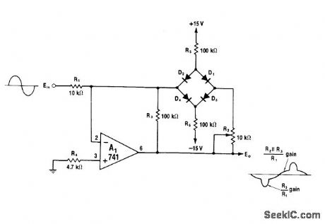
Diode bridge in feedback loop of opamp provides controlled amount of dead-band response. As value of R2 is increased from 0 ohms, voltage developed across R2. serves to raise dead-band level at which bridge opens and circuit amplifies with normal gain of R3/R1. Below dead-band level. bridge is blocked and circuit gain is equal to parallel combination of R2 and R3 divided by R1. Use matched diodes such as CA3O19 for peaks below ±7 V; for higher peaks,.use 1N914s.-W.G. Jung, IC Op-Amp Cookbook, Howard W.Sams. Indianapolis IN.1974. p 207.
Reprinted Url Of This Article:
http://www.seekic.com/circuit_diagram/Basic_Circuit/VARIABLE_DEAD_BAND_RESPONSE.html
Print this Page | Comments | Reading(3)

Article Categories
power supply circuit
Amplifier Circuit
Basic Circuit
LED and Light Circuit
Sensor Circuit
Signal Processing
Electrical Equipment Circuit
Control Circuit
Remote Control Circuit
A/D-D/A Converter Circuit
Audio Circuit
Measuring and Test Circuit
Communication Circuit
Computer-Related Circuit
555 Circuit
Automotive Circuit
Repairing Circuit
Code: