Signal Processing
Programmable_DIE_DCE_transceiver
Published:2009/7/24 2:06:00 Author:Jessie | From:SeekIC


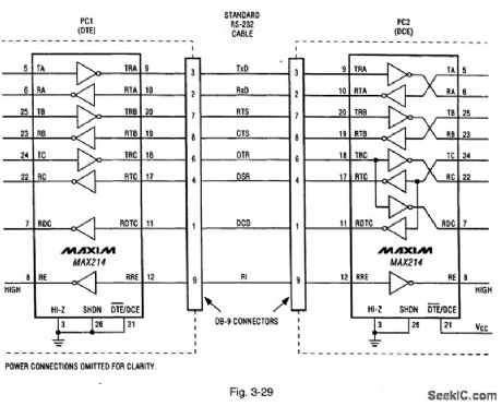
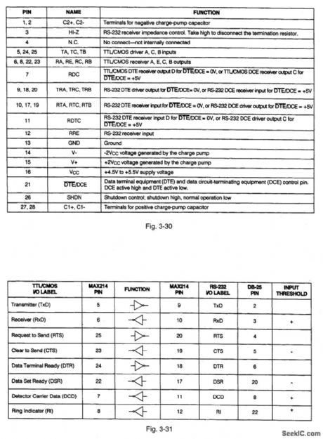
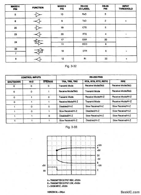
Figure 3-29 shows a typical application circuit (where two PCs have both DTE and DCE operation) for the MAX214. Figures 3-30, 3-31, 3-32, and 3-33 show the pin descriptions. Figure 3-34 shows the scope display for transmitter outputs when exiting shutdown. This IC provides a software-configurable DTE (data terminal equipment) or DCE (data circuit-terminating equipment) port RS232 interface. Either DTE or DCE is selected using the DTE/DCE pin (21). This IC eliminates the need to swap cables when switching between DTE and DCE configurations. MAXIM NEW RELEASES DATA BOOK, 1995, P, 2-69, 2-70, 2-72, 2-73, 2-74.
Reprinted Url Of This Article:
http://www.seekic.com/circuit_diagram/Signal_Processing/Programmable_DIE_DCE_transceiver.html
Print this Page | Comments | Reading(3)

Article Categories
power supply circuit
Amplifier Circuit
Basic Circuit
LED and Light Circuit
Sensor Circuit
Signal Processing
Electrical Equipment Circuit
Control Circuit
Remote Control Circuit
A/D-D/A Converter Circuit
Audio Circuit
Measuring and Test Circuit
Communication Circuit
Computer-Related Circuit
555 Circuit
Automotive Circuit
Repairing Circuit
Code: