
Circuit Diagram
Index 1095
225_MHz_13_W_AMPLIFIER_
Published:2009/7/4 20:45:00 Author:May
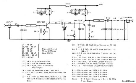

Suitable for use in FM transmitters for 220-225 MHz amateur radio bandBandwidth is about 10 MHz for ±0.5 dB Low-pass filter provides about 60-dB attenuation of second harmonic. Microstrip matching network simplifies construction. Supply 13-Watt Microstdp Amplifier for 220-225 MHz FM tranBandwidth is about 10 MHz for t0.5smitters for 220-225 MHz amateur ing network simplifies construction. Supply voltage is 12.5 V.-J. Hatchett and T. Sallet ''13-Watt Microstdp Amplifier for 220-225 MHz Operation, , Motorola, Phoenix, AZ, 1975, AN728, p 3. (View)
View full Circuit Diagram | Comments | Reading(663)
VHF_POWER_AMPLIFIER
Published:2009/7/4 20:24:00 Author:May
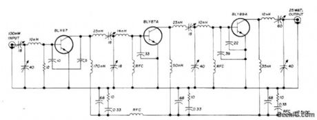
Three-stage 25-W225-MHz power amplifier module for FM apρlications uses three Amperex power transistors,Input and output are 50 ohms With 100-mW input signal,output is 25 W. Four capacitive dividers serve for input, output, and interstage matching. Collectors are shunt-fed. Three decoupling networks prevent seff-oscillation. Ampilfer can withstand output mismatches as high as 50:1 without damage.-E. Noll, VHF/ UHF Single-Frequency Conversion, Ham Radio, April 1975, p 62-67. (View)
View full Circuit Diagram | Comments | Reading(781)
The basic circuit diagram of LED
Published:2011/8/1 21:31:00 Author:Ecco | Keyword: basic circuit , LED

LEDs are current controlled devices, the current limiting resistor must be added in order to ensure their normal work. The basic circuit shownof LEDis shown as Figure 1.
(View)
View full Circuit Diagram | Comments | Reading(576)
Testing high, low frequency transistor circuit diagram
Published:2011/8/1 22:05:00 Author:Ecco | Keyword: Testing circuit, high frequency transistor , low frequency transistor

Method: PNP transistor is connected according to the figure a; NPN transistor is connected according to the figure b. In the figure, R is 2OkΩ limiting resistor, and power supply voltage E is l2V, V is the multimeter voltage and current files (it should be allocated the file with slightly larger than l2V).
(View)
View full Circuit Diagram | Comments | Reading(1214)
CRYSTAL_FM_DETECTOR_
Published:2009/7/4 20:17:00 Author:May

Exar XR-215 PLL IC is operated as crystal-controlled phase-locked loop by using crystal in place of conventional timing capacitor.Crystal should be operated infundamental mode Typical pull-in rangeis±1kHz at l0 MHz.-″Phase-Locked Loop Data Book,'' Exar Integrated Systems,Sunnyvale,CA,1978,p 21-28 (View)
View full Circuit Diagram | Comments | Reading(948)
CALL_ALERT
Published:2009/7/4 20:10:00 Author:May
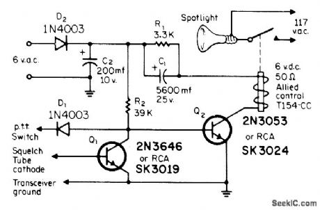
Developed to trigger relay when signal arrives at squelch tube in GE Progress Line 2-meter FM receiver. Relay is held energized about 2 s, determined by C1-R1, then deenergized for at least 25 s. Used for flashing red spotlight in room that is too noisy for hearing bell or buzzer. Circuit is easily adapted for any other FM receiver having squelch stage. Control circuit responds to small change in voltage at cathode of squelch tube. With no carrier present, tube conducts and places positive voltage at face of Q1, making it conduct and turn off Q2.When carrier arrives, Q1, restores bias to Q2, turning on relay. Connection to push-to-talk switch keeps lamp from flashing during transmission.-L. Waggoner, The WA0QPM Call Alert, CQ, May 1971, p 48-49 (View)
View full Circuit Diagram | Comments | Reading(990)
AFC_AMPLIFIER_
Published:2009/7/4 20:03:00 Author:May
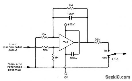
Simple DC amplifier can be added to AFC circuit of FM tuner to eliminate tuning errors over entire lock-in range.-J. S.Wilson, Improved A.F.C. for F.M. Tuners, Wireless World, July 1974, p 239. (View)
View full Circuit Diagram | Comments | Reading(1094)
IF_AND_STEREO_DEMODULATOR
Published:2009/7/4 19:58:00 Author:May

National LM3089 IC and LM1310 PLL FM stereo demodulator provide all circuits required between FM tuner and inputs to power amplifiers of stereoreceivor Use of 10.7- MHz ceramic filters eliminates all but one IF alignment step. AFC output from pin 7 of IF strip drives center-tune meter.Wide bandwidth of detector and audio stage in IF strip is more than adequate for stereo receivers. Audio stage can be muted by input voltage to pin 5. Demodulator lC includes automatic stereo/monaural switching and l00-mA stereo indicator lamp driver. Optional 300-pF capacitor on pin 6 of LM3089 can be used to limit bandwidth.- Audio Handbook, National Semiconductor, Santa Clara, CA, 1977, p 3-18-3-23. (View)
View full Circuit Diagram | Comments | Reading(3391)
OPAMP_DRIVE_FOR_LED_TUNING_LAMPS_
Published:2009/7/4 19:47:00 Author:May

Opamp with l00k feedback resistor gives gain of 10 as optimum compromise for driving two LED tuning indicators in FM receiver,-R. D.Post, F.M Tuning Indicator, Wireless World,May 1975,p 220. (View)
View full Circuit Diagram | Comments | Reading(821)
ANALOG_PLL_AS_FM_DEMODULATOR
Published:2009/7/4 19:42:00 Author:May

Upper frequency limit of about 50 MHz for NE562 and other monolithic analog phase-locked loops complicates construction of FM telemetry receivers that directly demodulate standard 88-108 MHz FM broadcast signals. Circuit shown solves problem, with only small amount of signal preconditioning, by first converting RF carrierto 10.7 MHz with conventional superheterodyne front end, then applying signal to phase detector of PLL with VCO set to run free at 10.7 MHz. Input sensitivity is less than 30 μV, and audio output is greater than 100 mV.-E. Murthi, Monolithic Phase-Locked Loops-Analogs Do All the Work of Digitals, and Much More, EDN Magazine, Sept. 5, 1977, p 59-64. (View)
View full Circuit Diagram | Comments | Reading(1972)
DEVIATION_METER
Published:2009/7/4 5:38:00 Author:May

Uses simple crystal oscillator combined with fixed or tunable FM receiver and CRO to show carrier shift on either side of center frequency,Vertical amplifier of CRO should be direct-coupled. To calibrate, tune oscillator either 10 or 15 kHz above or below second oscillator of receiver, and calibrate screen of CR0 accordingly. 0ne calibration oscillatoris sufficient since transmitter usually deviates equally well both ways.-V.Epp,FM Deviation Meters,73 Magazine, March 1973,p 81-83. (View)
View full Circuit Diagram | Comments | Reading(1293)
21_75MHz_DIODE_RECEIVER
Published:2009/7/4 5:31:00 Author:May
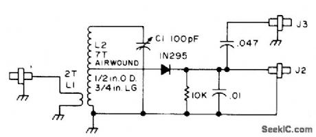
Covers 6-meter band and most 2-meter FM receiver oscillators near 45 MHz. Circuit is essentially that of crystal detector. Jack J3 gives AF output, and J2 gives DC output for meter.-B. Hoisington, Tuned Diode VHF Receivers, 73 Magazine, Dec. 1974, p 81-84. (View)
View full Circuit Diagram | Comments | Reading(1096)
1_GHz_amplifier_mixer
Published:2009/7/23 22:21:00 Author:Jessie
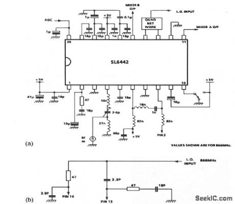
This circuit shows an SL6442 used as an amplifier/mixer suitable for cordless or cellular telephones, pagers, and any low-power receiver operating at frequencies up to 1GHz. The SL6442 contains a low-noise amplifier with AGC and two mixers for use in I and Q direct-conversion receivers or image-canceling in superhet receivers, with a single 5-V supply at a typical current of 4 mA. In this circuit, the local-oscillator signal is applied through a quad network (Fig. 2-33B).RF is applied at pin 4, AGC at pin 20, and mixer outputs are taken from pins 11 and 15. (View)
View full Circuit Diagram | Comments | Reading(900)
FENCING_TOUCH_TIMER
Published:2009/7/23 22:20:00 Author:Jessie
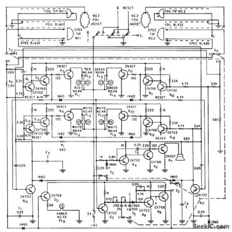
Detects touches in either epee or foil fencing, determines if touch is held long enough to score point, then starts timing interval in which other fencer may also score. Lamps indicate status of match. Loudspeaker sounds tone when sequence of touches is correct, and switch S1 must then be reset for next scoring sequence.-W. R. Durrell, Electronic Judging of Fast-Moving Sports Contests, Electronics, 32:32, p 114-115. (View)
View full Circuit Diagram | Comments | Reading(1679)
TWO_WAY_SAMPLING_SWITCH
Published:2009/7/23 22:20:00 Author:Jessie
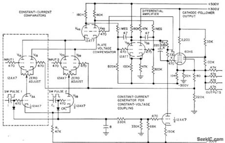
Uses two compensated comparators V1 and V2 whose currents are maintained constant by V3A and V3B, while V4 maintains constant plate voltage on these tubes. May be expanded to multi-way unit by adding input selector circuits, or may be used as precision cathode follower by eliminating selector. Circuit has near-infinite input impedance and near-zero output impedance. Comparator compensation permits accuracy of 0.1% over range of -100 to +100 V.-R. Benjamin, Electronic Switch Doubles as Cathode Follower, Electronics, 31:3, p 81-83. (View)
View full Circuit Diagram | Comments | Reading(713)
Parallel_power_RS_232_transceivers
Published:2009/7/23 22:20:00 Author:Jessie
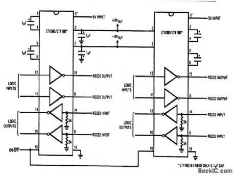
This circuit shows two LT1080 RS-232 transceivers operated from 5-V power. Twice the output current is available for external use. Also, the circuit produces ±9-V power output, as needed. The circuit eliminates two capacitors, although individual charge-pump capacitors are still needed on each device. (View)
View full Circuit Diagram | Comments | Reading(488)
LED_TUNING_INDICATOR
Published:2009/7/4 5:26:00 Author:May

One LED is mounted at each end of tuning scale. Tuning pointer is moved away from whichever LED is on, to dead spot at which both are off, to obtain correct tuning point. Advantages of lights-off tuning include minimum current drain and indication of even very slight mistuning by having one light come on even slightly. Adjust VR1 to give wide enough dead spot so LEDs do not flicker on loud speech or music.-H. Hodgson, Simpler F.M.Tuning Indicator, Wireless World, Sept. 1975, p 413. (View)
View full Circuit Diagram | Comments | Reading(902)
MAGNETOSTRICTION_TV_REMOTE_CONTROL
Published:2009/7/23 22:20:00 Author:Jessie

Frequency of transistor oscillator is controlled by either of two lengths of nickel tubing, each looting inside form having two coil windings. One coil acts as driver and the other as pickup to provide feedback voltage for sustaining oscillation at control frequencies of 38.5 and 41.5 kc. Aluminum diaphragms on front ends of tubing increase acoustic output.-N. Frihart and J. Krakora, Ultrasonic Tones Select Tv Channels, Electronics, 31 :23, p 68-69. (View)
View full Circuit Diagram | Comments | Reading(670)
Sample_hold_circuit
Published:2009/7/23 22:20:00 Author:Jessie

Figures 2-20 and 2-21 show a typical application circuit and pin configuration/ switching-state, respectively, for the IH5040-IH5045/47. These general-purpose CMOS analog switches are latch-up proof, with 1-nA leakage current and less than 1-μA quiescent current. MAXIM HIGH-RELIABILITY DATA BOOK, 1993, P. 1-153. (View)
View full Circuit Diagram | Comments | Reading(1424)
Simple_RF_leveling_loop
Published:2009/7/23 22:19:00 Author:Jessie
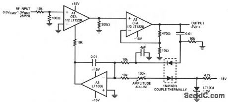
This circuit stabilizes the amplitude of an RF signal against variations in input, time, and temperature. A1 (an OTA, chapter 11) feeds current-feedback amplifier A2. The A2 output is sampled by the A3-biased gain-control configura-tion. The 4-pF capacitor compensates rectifier diode capacitance, which enhances output flatness versus frequency. The A1 ISET input current controls A1 gain, and allows overall output-level control. (View)
View full Circuit Diagram | Comments | Reading(645)
| Pages:1095/2234 At 2010811082108310841085108610871088108910901091109210931094109510961097109810991100Under 20 |
Circuit Categories
power supply circuit
Amplifier Circuit
Basic Circuit
LED and Light Circuit
Sensor Circuit
Signal Processing
Electrical Equipment Circuit
Control Circuit
Remote Control Circuit
A/D-D/A Converter Circuit
Audio Circuit
Measuring and Test Circuit
Communication Circuit
Computer-Related Circuit
555 Circuit
Automotive Circuit
Repairing Circuit