Basic Circuit
Simple_RF_leveling_loop
Published:2009/7/23 22:19:00 Author:Jessie | From:SeekIC

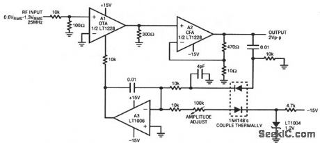
This circuit stabilizes the amplitude of an RF signal against variations in input, time, and temperature. A1 (an OTA, chapter 11) feeds current-feedback amplifier A2. The A2 output is sampled by the A3-biased gain-control configura-tion. The 4-pF capacitor compensates rectifier diode capacitance, which enhances output flatness versus frequency. The A1 ISET input current controls A1 gain, and allows overall output-level control.
Reprinted Url Of This Article:
http://www.seekic.com/circuit_diagram/Basic_Circuit/Simple_RF_leveling_loop.html
Print this Page | Comments | Reading(3)

Article Categories
power supply circuit
Amplifier Circuit
Basic Circuit
LED and Light Circuit
Sensor Circuit
Signal Processing
Electrical Equipment Circuit
Control Circuit
Remote Control Circuit
A/D-D/A Converter Circuit
Audio Circuit
Measuring and Test Circuit
Communication Circuit
Computer-Related Circuit
555 Circuit
Automotive Circuit
Repairing Circuit
Code: