
Circuit Diagram
Index 1088
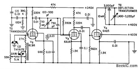
UPPERCASE_LOWERCASE_DRIVE_FOR_TV
Published:2009/7/5 21:25:00 Author:May
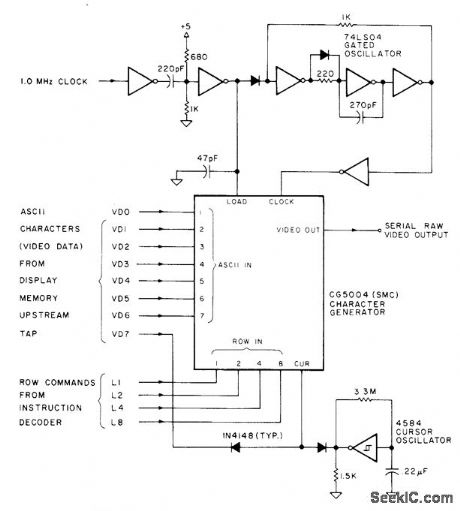
Standard Microsystems CG5004 alphamerle data-to-video converter provides both uppercase and lowercase characters and all numerals in serial video form for display as 7 x 9 character matrix on TV screen under microprocessor control. IC requires only single +5 V supply. Winking underline cursor is produced automatically by cursor oscillator. Internal shift register is part of IC. Raw video requires predistorting for clarity and addition of sync pulses before it can be fed to TV set.-D. Lancaster, TVT Hardware Design, Kilobaud, Jan. 1978, p 64-68. (View)
View full Circuit Diagram | Comments | Reading(653)
S25610 Microcomputer Dialing Integrated Circuit
Published:2011/7/29 3:18:00 Author:Michel | Keyword: Microcomputer Dialing, Integrated Circuit
S25610 is system microcomputer dialing integrated circuit that is widely used in communication telephone circuit.
First,Functions FeaturesS25610 integrated circuit contains pulse dialing generating circuit, key switch signal decoding circuit, the noise and static control circuits etc.
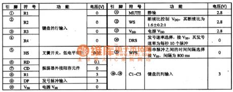
Second,Pins Functions and DataS25610 adopts feet 18 DIP generating circuit and its pins functions and data are shown as table 1.
Table 1:S25610 IC Pins Functions and Data (View)
View full Circuit Diagram | Comments | Reading(460)
High_repetition_rate_VPP_programming_supply
Published:2009/7/23 22:05:00 Author:Jessie
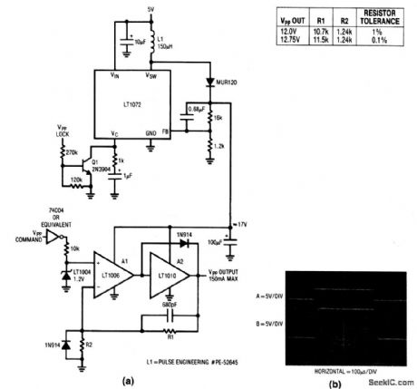
This circuit is similar to that of Fig.6-48, but with higher repetition rate, and with controlled rise time to eliminate overshoots (as shown in Fig.6-49B). (View)
View full Circuit Diagram | Comments | Reading(441)
SSB_generator
Published:2009/7/23 22:05:00 Author:Jessie

This circuit shows an SL6700 (Fig. 2-13) connected to form a no-adjustment SSB generator. The trim adjustment shown in dashed lines is only used for re-inserting a carrier (not required for basic SSB operation). Notice that the microphone input is applied through an SL6720 (Fig. 1-7). (View)
View full Circuit Diagram | Comments | Reading(1877)
AF_TONE_BURSTS
Published:2009/7/5 21:24:00 Author:May
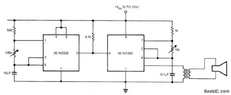
First 555 timer operates as slow astable multivibrator whose output is used to gate second timer operating as AF oscillator. Arrangement provides repeatable toneburst generation.-E. R. Hnatek. Put the IC Timer to Work in a Myriad of Ways. EDN Magazine. March 5. 1973. p 54-58. (View)
View full Circuit Diagram | Comments | Reading(508)
ZENER_DIODE_INCREASE_FIXED_PNP_REGULATOR’S_OUTPUT_VOLTAGE_RATINGS
Published:2009/7/5 21:23:00 Author:May
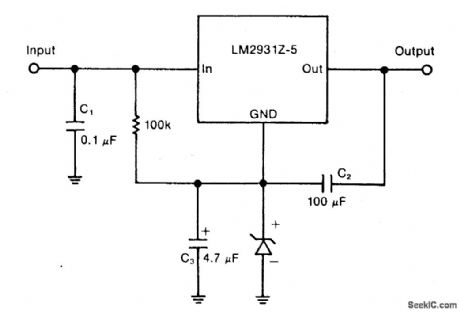
Circuit Notes
A zener diode in the ground lead of a fixed pnp regulator varies the voltage output of that device without a signiftcant sacriftce in regulation. The technique also allows the regulator to operate with output voltages beyond its rated limit. (View)
View full Circuit Diagram | Comments | Reading(0)
Phase locked loop secondary frequency conversion wireless transceiver circuit corresponds the industrial remote control GB
Published:2011/7/25 21:48:00 Author:Christina | Keyword: Phase, locked loop, secondary frequency, conversion, wireless, transceiver circuit, industrial, remote control, GB

The NT230 launch module uses the special import high stability crystal (it is not the surface acoustic wave resonator). It outputs the stable 230MHz radio frequency FSK signal, and the emission current is very small, when the power is 5V/8mA, the output voltage is 110dBuV (75Ω load).
The NR230 receiving module diagram is as shown in figure 1, the modulated coded signal which is from the antenna is amplified and mixed by the circuit, then it is sent into the second mixer which is composed of the LA3372, after the original signal is detected out, it gets through the low-pass circuit and the amplification shaping circuit.
(View)
View full Circuit Diagram | Comments | Reading(1426)
S18100D Switch Power Supply Thick-film Integrated Circuit
Published:2011/7/29 3:27:00 Author:Michel | Keyword: Switch, Power Supply, Thick-film, Integrated Circuit

S18100D is a kind of switch power supply thick-film integrated circuit that is widely used in Toshiba 219X6Y color TVs.
First,Functions FeaturesS18100D integrated circuit contains drive pulse output circuit, over-voltage and over-current protection circuit, standby control circuit and some other auxiliary functions circuit.
Second,Pins Functions and FeaturesS18100D IC adopts feet 11 package and its pins functions and data are shown as table 1.
Table 1:S18100D IC Pins Functions and Data (View)
View full Circuit Diagram | Comments | Reading(716)
Off_isolation_tests
Published:2009/7/23 22:05:00 Author:Jessie

Figure 2-W shows a test circuit for measuring the isolation between channels (when the channel switch is open) for the MAX301/3/5. Typical isolation is 72 dB, (View)
View full Circuit Diagram | Comments | Reading(556)
LEAKAGE_TESTER_1
Published:2009/7/23 22:05:00 Author:Jessie

High-reliability current-detecting Schmitt trigger responds to nanoampere inputs for leakage testing of capacitors, diodes, and insulation, yet is not damaged or even affected by overloads of 1,000 v at input. Input of 300 no will trigger output relay.-P. Lefferts, Schmitt Triggers on Nanoamp Inputs, EEE, 14:6, p 91. (View)
View full Circuit Diagram | Comments | Reading(970)
SING_AROUND_TRIGGER_GENERATOR
Published:2009/7/23 22:05:00 Author:Jessie

Electrical echo signals generated by receiving transducer pass through 10-Mc tuned amplifier to trigger generator that delays selected detected echo and combines it with undetected echo in fast series-transistor coincidence circuit to obtain trigger output pulse for transmitter of ultrasonic velocity measuring system.-R. L. Forgacs, Precision Ultrasonic Velocity Measurements, Electronics, 33:47, p 98-100. (View)
View full Circuit Diagram | Comments | Reading(1081)
Charge_injection_tests
Published:2009/7/23 22:05:00 Author:Jessie
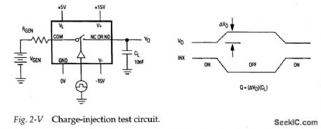
Figure 2-V shows a test circuit for measuring charge injection for the MAX301/ 3/5. Notice that charge injection (Q) is measured in coulombs (C). A pulse is applied to the control pin and the difference in output voltage is noted. Q is calculated when the difference in output voltage is divided by the capacitance at the output. Typical charge injection is 10 to 15pC. (View)
View full Circuit Diagram | Comments | Reading(738)
PULSE_COUNT_SAMPLE_TIME_RECORDER
Published:2009/7/23 22:04:00 Author:Jessie
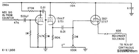
Amplifier and thyratron trigger feed pulse to solenoid pen of recorder, to record time of end of counting period, corresponding to instant at which counter delivers negative pulse.-C. F. Miller, New Phototransistor Tachometers Measure Missile Spin, Electronics, 35:25, p 33-35. (View)
View full Circuit Diagram | Comments | Reading(642)
PLUG_IN_TOOL_USE_TIMER
Published:2009/7/23 22:14:00 Author:Jessie
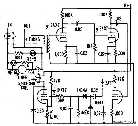
Serves as running time meter for soldering suns, electric drills, and other portable power tools. Tool is plugged into outlet on timer, eliminating need for connections lo switch of device under test. Load capacity is from 25 to 1,000 w. R. L. lves, Circuit Times Operation of Portable Tools, Electronics, 31:5, p 62-64. (View)
View full Circuit Diagram | Comments | Reading(566)
CX20106/CX20106A (TV) infrared remote control receiving preamplifier circuit
Published:2011/8/1 8:16:00 Author:Christina | Keyword: TV, infrared, remote control, receiving, preamplifier circuit
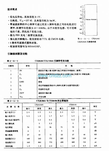
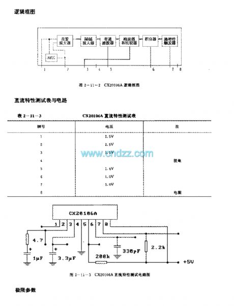
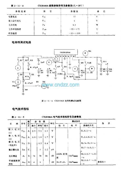

The CX20106/CX20106A is designed as the infrared remote control receiving preamplifier bipolarity circuit that can be used in the TV application. The internal circuit is composed of the preamplifier, the ABLC, the amplitude limiting amplifier,the bandpass filter, the peak value wave detector and the waveform shaping circuit. The CX20106A is the improved model of CX20106, the difference between the CX20106 and CX20106A is the electrical parameter.
Features
Low power voltage, the typical value is 5V.Low power consumption. When Vcc=5V, the typical power consumption is 9mW.You can change the centre frequency of the bandpass filter by changing the resistance between the pin-5 and the power supply.It can be connected with the PIN photoelectric diode. It is in the 8-pin single row DIP plastic package.The matching model is M50462AP.
(View)
View full Circuit Diagram | Comments | Reading(2793)
22_KC_SONAR
Published:2009/7/23 22:14:00 Author:Jessie
Amplifier is coupled to sonar transducer through 8:1 step-up transformer and resistor-varistor network. Circuit feeds cathode-ray display that protects V2 from overload and possible blocking during echo return time. Receiver gain is 137 db.-L. H. Dulberger, Sonar to Survey Arctic Ocean Shelf Transmits Through Ice and Water, Electronics, 34;31, p 44-45. (View)
View full Circuit Diagram | Comments | Reading(1127)
Fault_tolerant_mux
Published:2009/7/23 22:14:00 Author:Jessie

Figure 2-11 shows how the MAX328/29 (Figs, 2-O, 2-P) can be converted to a fault-tolerant mux. The internal diodes limit the voltage at the input to±15.7 V (±15-V supplies). No external diodes are required. The resistors limit power dissipation to 0.28 W when a 120-Vac fault occurs. MAXIM HIGH-RELIABILITY DATA BOOK, 1993, P. 1-6. (View)
View full Circuit Diagram | Comments | Reading(599)
S14133-MLP28 Frequency Synthesizer Integrated Circuit
Published:2011/7/29 2:16:00 Author:Michel | Keyword: Frequency Synthesizer, Integrated Circuit
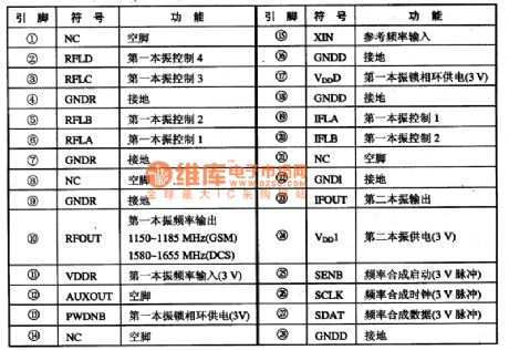
(View)
View full Circuit Diagram | Comments | Reading(501)
Digitally_controlled_4__to_20_mA_current_loop_generator
Published:2009/7/23 22:14:00 Author:Jessie
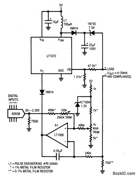
This 5-V circuit uses a servo-controlled dc/dc converter to generate the compliance voltage necessary for loop-current requirements in industrial-control (valves, etc.) applications. The circuit will drive 4 to 20 mA into loads as high as 2200 Ω (44 V compliance) and is inherently short-circuit protected. The digital input permits easy interface to digital systems. (View)
View full Circuit Diagram | Comments | Reading(937)
BA6340 (VCR) infrared remote control receiving preamplifier circuit
Published:2011/8/1 8:08:00 Author:Christina | Keyword: VCR, infrared, remote control, receiving, preamplifier circuit

The BA6340 is designed as the infrared remote control receiving preamplifier circuit that can be used in the VCR application. The internal circuit is composed of the receiving circuit, the amplifier circuit, the peak value detection circuit, the shaping circuit and the Schmidt output circuit. This device is in the 8-pin single row DIP plastic package.
(View)
View full Circuit Diagram | Comments | Reading(527)
| Pages:1088/2234 At 2010811082108310841085108610871088108910901091109210931094109510961097109810991100Under 20 |
Circuit Categories
power supply circuit
Amplifier Circuit
Basic Circuit
LED and Light Circuit
Sensor Circuit
Signal Processing
Electrical Equipment Circuit
Control Circuit
Remote Control Circuit
A/D-D/A Converter Circuit
Audio Circuit
Measuring and Test Circuit
Communication Circuit
Computer-Related Circuit
555 Circuit
Automotive Circuit
Repairing Circuit