
Circuit Diagram
Index 1087
DIGITALLY_PROGRAMMABLE_ATTENUATOR_
Published:2009/7/5 21:34:00 Author:May

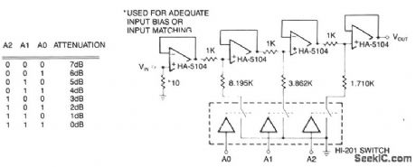
The first stage is a simple buffer used to isolate the signal source from the attenuator stages to follow. Each of the subsequent stages is preceded by a voltage divider formed by two resistors and CMOS switch. Provided that the CMOS switch for each stage is closed, the drive signal will be attenuated according to the basic voltage divider relationship at each stage. In the event a switch is open, nearly all of the signal strength will be passed to the next stage through the 1-KΩ resistor. The amplifiers act as buffers for divider networks and reduce the interaction between stages. Eight levels of attenuation are possible with the circuit as illustrated, but more stages could be added. Each divider network must be closely matched to the resistor ratios shown or the level of attenuation will not match the levels in the logic chart. (View)
View full Circuit Diagram | Comments | Reading(614)
LOW_COST_ULTRA_HIGH_VOLTAGE_GENERATOR
Published:2009/7/5 21:34:00 Author:May
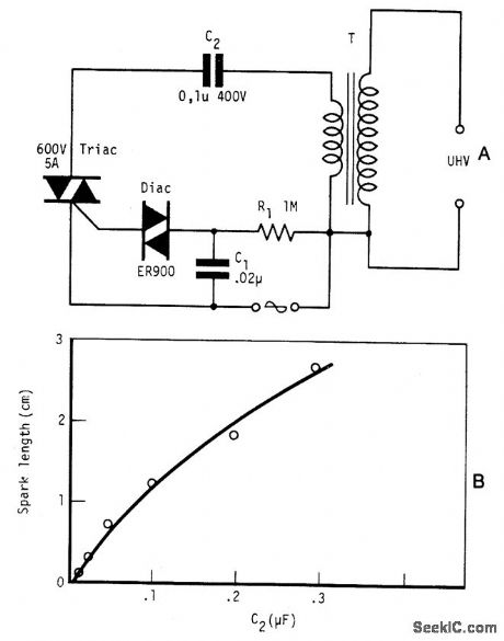
Circuit NotesBy repetitively charging and discharging a capacitor through the primary of an induction coil with a high voltage, an ultra high emf is induced in the secondary. Switching is performed by the triac, triggered by the disc at times set by C1 and R1. With a 12 V car ignition coil for example, the length of sparkgap obtained is 12 mm of air for C2 = 0.1μF. If the dielectric strength of air is assumed to be 3 kV/mm, this spark-gap length corresponds to 36 kV. From the curve shown in Fig. B, care must be taken in keeping the value of C2 below 1μF as the coil is liable to be seriously damaged at this value of C2. Power consumption is only about one watt. (View)
View full Circuit Diagram | Comments | Reading(0)
TIME_INTERVAL_ANALYZER
Published:2009/7/23 22:09:00 Author:Jessie
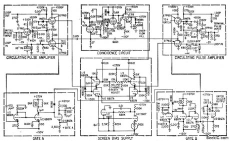
Gives high resolution (better than 1 millimicrosec) for multichannel measurements of short-life nuclear particles. Two pulses, defining time interval, are fed into the same loop-forming ends of two transmission lines. By making coincidence circuit spacing slightly smaller on terminal pulse lines than on initial pulse lines, terminal pulse is made to overtake initial pulse. Pulses approach coincidence al 1 millimicrosec per transit, so count of transits before coincidence gives time interval-H. W. Lefevre and J. T. Russell, Vernier Chronotron limes Nuclear Particle Flight, Electronics, 32:10, p 44-47. (View)
View full Circuit Diagram | Comments | Reading(783)
Remote_control_recetver
Published:2009/7/23 22:09:00 Author:Jessie
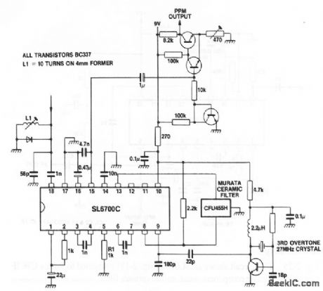
This circuit shows an SL6700 (Fig. 2-13) used as a complete 27-MHz remote-control receiver (such as used for most model controls). (View)
View full Circuit Diagram | Comments | Reading(1542)
CURRENT_CONTROLLED_WlEN
Published:2009/7/5 21:32:00 Author:May
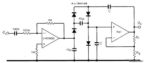
Small variations in input voltage to National LM3900 current-mode amplifier change frequency of fourdiode current-controlled Wien bridge over range from 10 to 50,000 Hz, with frequency being proportional to control current. Value of C is 700 pF. Ratio of R2 to sum of R1 and R2 should be greater than 3 to give voltage gain needed.-K. Kraus. Oscillator with Current-Controlled Frequency, Wireless World, Aug, 1974, p 272. (View)
View full Circuit Diagram | Comments | Reading(474)
A_C_ZERO_LOCATOR
Published:2009/7/23 22:09:00 Author:Jessie

Locales zero of a-c voltage within 0.1 microsec for 50-kc input signal. Operation is independent of input signal amplitude between 0.15 and 30 v p-p. Used for accurate measurement of lime interval between given number of cycles of ex ponentially decaying 50.kc signal.-L. Costrell, A.C Zero locator, Electronics, 31:3, p 98-101. (View)
View full Circuit Diagram | Comments | Reading(572)
Homemade 0/12V wireless control switcher circuit
Published:2011/7/25 22:30:00 Author:Christina | Keyword: Homemade, 0/12V, wireless control, switcher circuit

Operating principle: Figure 1 is the circuit of the switcher transmitter part, figure 2 is the circuit of the switcher receiving switch part. In figure 1, when the 0/12V output port of the digital machine has the 12V voltage, it outputs the 5V voltage through the IC1, the A1 radio remote control dedicated transmitter module gets power to operate, the built-in miniature antenna outputs the ultra-high frequency modulation signal.
In the effective receiving range, when the receiving circuit (figure 2) receives the modulating signal, the A2 dedicated receiver module outputs the high level pulse, the transistor VT1 conducts to drive the relay J to finish the switch between the two high frequency heads.
(View)
View full Circuit Diagram | Comments | Reading(553)
SONAR_AUDIO_SELECTION_GATE
Published:2009/7/23 22:08:00 Author:Jessie

Triangular sliding gate of sonar target classifier selects from channel positions the sample chosen for monitoring by sonar operator-trainee, with smooth transition from one channel to another.-M. H. Damon, Jr., Tape Target Classifier Trains Sonar Operators, Electronics, 33:13, p 65-69. (View)
View full Circuit Diagram | Comments | Reading(972)
Homemade simple remote control switch circuit
Published:2011/7/26 1:25:00 Author:Christina | Keyword: Homemade, simple, remote control, switch circuit

The IC1 is the color TV remote control receiver, pin-1 is the ground port, pin-2 is the +5V power supply port, pin-3 is the signal output port, it has the +3.6V voltage when it does not receive the signal, and it has the 0V voltage when it receives the signal, IC2 is the CD4017 decimal counter / decoder IC.
The 220V AC power supply is reduced, rectified and filted by the circuit to change into the 12V DC voltage that can be used as the operating voltage of the relay, the +12V current is limited by R2 and stabilized by VD to be the +5V current. When the circuit is in the static state, the T1 conducts, Q0=1, the indicator light LED turns on.
(View)
View full Circuit Diagram | Comments | Reading(1514)
Channel_capacitance
Published:2009/7/23 22:06:00 Author:Jessie

Figures 2-Y and 2-Z show test circuits for measuring channel capacitance with the channel switch open and closed. Typical capacitance is 12 pF with the channel open and 39 pF when the channel is closed. (View)
View full Circuit Diagram | Comments | Reading(476)
UNDERSEA_PROPAGATION_RECEIVER
Published:2009/7/23 22:06:00 Author:Jessie

Amplified output of receiving transducer is fed to receiver gate that acts like switch in that output appears only when pulse is applied. Receiver is thus sensitive only for short intervals of time in which return is expected. Output of receiver gate is detected by V8 and filtered to get pulse envelope for crt. Receiver pulse is also amplified by V9 and used to charge capacitor in boxcar generator, so amplitude of pulse is remembered in interval between pulses. To make boxcar generator forget old amplitude when another pulse arrives, receiver gate is shaped into narrow pulse used to discharge capacitors through V11 just before arrival of next pulse.-W. C. Gore, Ultrasonics Tests Undersea Propagation, Electronics, 31:35, p 32-35. (View)
View full Circuit Diagram | Comments | Reading(644)
Homemade multi-purpose remote control circuit
Published:2011/7/25 22:20:00 Author:Christina | Keyword: Homemade, multi-purpose, remote control circuit


This remote controller uses the miniaturization wireless remote control 4-bit special component which is produced by the XinLi electronic instrument Co., LTD, it is composed of a 4-bit buckle type transmitter, the power supply uses the A23 type 12V battery with small size. The recevier circuit is the KL668 type, the power supply is 9V DC, the voltage of the control relay is decided by the relay, the relay in this figure is 12V. This receiving circuit has strong anti-interference ability, the control distance is 20-40 miles.
(View)
View full Circuit Diagram | Comments | Reading(804)
Crosstalk_tests
Published:2009/7/23 22:06:00 Author:Jessie

Figure 2-X shows a test circuit for measuring the isolation between channels (or the lack of crosstalk when the channel switches are closed) for the MAX301/3/5.Typical crosstalk isolation is 90 dB. (View)
View full Circuit Diagram | Comments | Reading(567)
Hitachi CMT2988 pincushion correction circuit
Published:2011/7/25 22:12:00 Author:Christina | Keyword: Hitachi, pincushion correction circuit
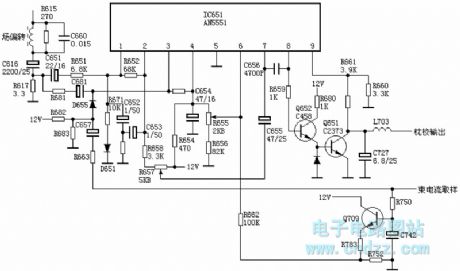
The 4V sawtooth wave voltage (peak-peak value) of the R617 adds to the pin-1 of IC651 through the C651 and R651, this voltage is amplified and disposed by the IC651, the pin-2 of IC651 outputs the 2V (peak-peak value) concave parabolic wave voltage, this voltage is integrated by the C653, C652 and R666, the R657 adjusts the amplitude of the parabolic wave, then it adds to the pin-7 of IC651 through the C655, it is amplified and reshaped by the IC651, the pin-8 outputs the convex parabolic wave voltage, this voltage is followed by the Q652's emitter and it is amplified by the Q651 to form the 9V (peak-peak value) concave parabolic wave voltage on both ends of C727.
(View)
View full Circuit Diagram | Comments | Reading(600)
SAA301OT Remote Transmitter Integrated Circuit
Published:2011/7/29 8:39:00 Author:Michel | Keyword: Remote Transmitter, Integrated Circuit

SAA301OT remote transmitter integrated circuit is widely used in video and audio system.
SAA30lOT contains integrated circuit keyboard switch decoding circuit and remote control launch carrier signal circuit, etc.This IC adopts feet 28 DIP package and its pins and data are shown as table 1.
Table 1 :SAA3010T IC Pind Functions and Data (View)
View full Circuit Diagram | Comments | Reading(724)
MEMORY_SAVE_ON_POWER_DOWN
Published:2009/7/5 21:28:00 Author:May
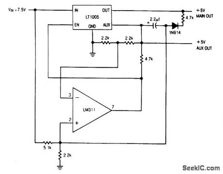
Circuit NotesThe auxiliary output powers the memory, while the main output powers the system and is connected to the memory store pin. When power goes down, the main output goes low, commanding the memory to store. The auxiliary output then drops out. (View)
View full Circuit Diagram | Comments | Reading(0)
FAIL_SAFE_ALARM
Published:2009/7/5 21:28:00 Author:May

Circuit monitors status of microprocessor system and energizes lamp or other alarm indicator to indicate when CPU halts or power is lost. Input is TTL-compatible, and output can drive loads up to 130 mA at 30 V.-J. Elias, Alarm Driver Is Fail-Safe, EDN Magazine, May 20, 1975, p 76. (View)
View full Circuit Diagram | Comments | Reading(698)
TRANSISTOR_MEASUREMENTS_AT_100_MC
Published:2009/7/23 22:06:00 Author:Jessie

Used to measure h-fe at 100 Mc, where all circuit parameters become more significant and make accurate measurements difficult. Circuit has provisions for separating measured signal from noise, high-gain pre-meter amplifier, and accurate method of metering r-f level. Maximum error is under 5%.-W. H. Hamlin, How to Measure h-fe et 100 mHz, EEE, 13:6, p 70-72. (View)
View full Circuit Diagram | Comments | Reading(514)
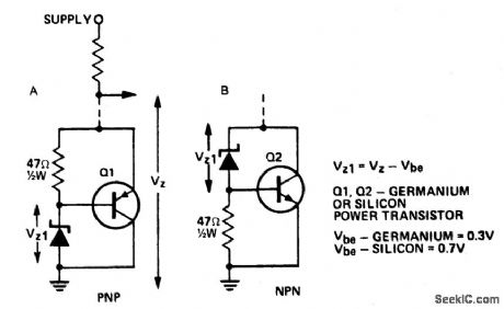
INCREASING_THE_POWER_RATING_OF_ZENER_DIODES
Published:2009/7/5 21:27:00 Author:May
Circuit Notes
A power transistor can be used to provide a high powered zener voltage from a low wattage zener. A 400 mW zener can be used where a 10 watt zener is required or a 1W zener cait be used where a 50 to 80 watt zener is required by using appropriate transistors for Q1 and Q2 in the circuits shown. Where low rating is required, Q1 would be an ASZ 15 (germanium) or an AY9140 (silicon). Q2 could be a 2N2955 (silicon). For higher powers, Q1 should be an ASZ18 (germanium) or a 2N2955 (silicon) and Q2 a 2N3055 (silicon) or an AY8149 (silicon). A heatsink on the transistor is required. The circuit in A has the advantage that power transistors can be bolted directly on to a chassis which may serve as a heatsink. (View)
View full Circuit Diagram | Comments | Reading(0)
COLD_CATHODE_SAMPLING_COUNTER
Published:2009/7/23 22:06:00 Author:Jessie
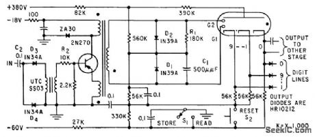
Transistor-blocking oscillator drives cold-cathode counter tube to give long-life decade counter having low power consumption. Used in automatic recorder for data from several hundred radioactive samples per day. Maximum repetition rate is 200 pps.-H. Sadowski and M. E. Cassidy, How Transistor Drives Cold-Cathode Counter, Electronics, 32:38, p 46-47. (View)
View full Circuit Diagram | Comments | Reading(598)
| Pages:1087/2234 At 2010811082108310841085108610871088108910901091109210931094109510961097109810991100Under 20 |
Circuit Categories
power supply circuit
Amplifier Circuit
Basic Circuit
LED and Light Circuit
Sensor Circuit
Signal Processing
Electrical Equipment Circuit
Control Circuit
Remote Control Circuit
A/D-D/A Converter Circuit
Audio Circuit
Measuring and Test Circuit
Communication Circuit
Computer-Related Circuit
555 Circuit
Automotive Circuit
Repairing Circuit