
Circuit Diagram
Index 1101
60_KC_HYDROPHONE_RECEIVER
Published:2009/7/23 22:30:00 Author:Jessie
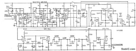
Shore-based receiver responds to four signal frequencies in 60-kc region, at levels as low as 1 microvolt, coming from receiving hydrophone through up to 15,000 feet of 120-ohm underwater cable. Output of cathode follower V6B is connected to four Foster-Seeley discriminators (not shown) that demodulate signals for driving recorder. Used in monitoring performance of four underwater mines while test ship passes over.-M. J. Aucremanne and D. D. Woolston, Telemeter System Relays Undersea Ordnance Data, Electronics, 31:41, p 84-87. (View)
View full Circuit Diagram | Comments | Reading(810)
UJT_INTERVAL_TIMER
Published:2009/7/23 22:30:00 Author:Jessie
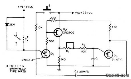
Inexpensive relay provides excellent timing accuracy and high isolation in circuit using power gain of emitter junction of ujt Q1. Timing is determined by R1, R2, and C1.-N. H. Kadivnik, Interval Timer, EEE, 12:5, p 75. (View)
View full Circuit Diagram | Comments | Reading(631)
Power_supply_monitor
Published:2009/7/23 22:30:00 Author:Jessie
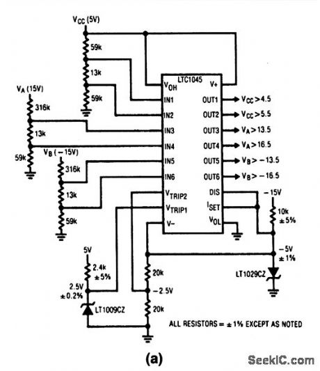
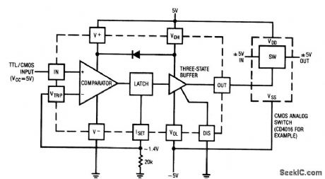
This circuit shows an LTC1045 used as a power-supply monitor. The outputs of three power supplies are tied to the positive inputs through an appropriate resistive voltage divider. The divider ratio is set so that the voltage into the comparator (Fig. 6-61B) equals the reference on the inverting input when the power-supply voltage is at a critical level. (View)
View full Circuit Diagram | Comments | Reading(2866)
SIMPLE_SAWTOOTH
Published:2009/7/23 22:30:00 Author:Jessie
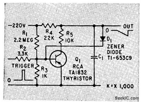
Uses semiconductor switch Q1, whose amplitude is controlled by zener diode D1. Operation on only small part of R-C charging curve helps make out put pulse widths, amplitudes, and waveform timing independent of active elements in circuit.-C. A. Von Urff and R. W. Ahrons, How to Generate Accurate Sawtoolh and Pulse Waves, Electronics, 32:50, p 64-66. (View)
View full Circuit Diagram | Comments | Reading(540)
Basic_step_down_voltage_regulator
Published:2009/7/23 22:29:00 Author:Jessie
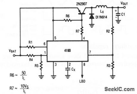
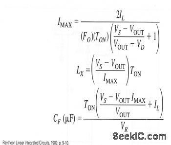
Figure 4-3 shows a basic step-down voltage regulator, where loads are from 500 mW to 2 W. Component values are tailored to circuit requirements, as described for Fig. 4-2, except as:.
(View)
View full Circuit Diagram | Comments | Reading(640)
200_MC_BINARY_FOR_INTERVAL_TIMER
Published:2009/7/23 22:29:00 Author:Jessie
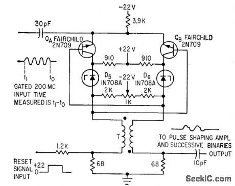
Gated 200-Mc input is fed to both emitters. Individual tenet diodes provide collector bias. Base bios is obtained from collector resistor load of opposite transistor. Potentiometer permits perfect balancing. Time intervals are measured accurately to 5 nsec.-C. S. Coffey, VHF Counter Measures Time Iptervals Precisely, Electronics, 36:34, p 27-29. (View)
View full Circuit Diagram | Comments | Reading(611)
PULSE_WIDTH_MEASUREMENT
Published:2009/7/23 22:29:00 Author:Jessie
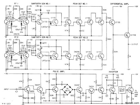
Develops two sawtooth waveforms of equal slope, one delayed relative to other by width of pulse to be measured. Control flip-flops turn both sawtooth generators off simultaneously, so difference in sawtooth peak amplitudes is proportional to pulse width being measured.-D. B. Dobson and L. L. Wolff, Automatic Test Equipment Checks Missile Systems, Electronics, 33:29, p 74-78. (View)
View full Circuit Diagram | Comments | Reading(648)
Bridge_amplifier_with_low_noise_compensation
Published:2009/7/23 22:29:00 Author:Jessie

Compensating capacitor C1 makes supply bypassing unnecessary. (View)
View full Circuit Diagram | Comments | Reading(0)
AUDITORIUM_ACOUSTICS_TIMER
Published:2009/7/23 22:28:00 Author:Jessie
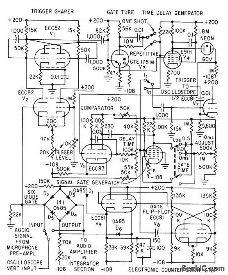
Can be set to accept any portion of incoming sound signal for feeding to electrostatic squarer and digital counter. Microphone preamp feeds gate input and trigger shaper. lime base consists of phantastron sawtooth generator and comparator giving delay time linearly variable from 0 to 120 millisec.-J. P. A. Lochner and P. Meffert, Electrostatic Squarer for Acoustic Measurements, Electronics, 33:35, p 66-68. (View)
View full Circuit Diagram | Comments | Reading(560)
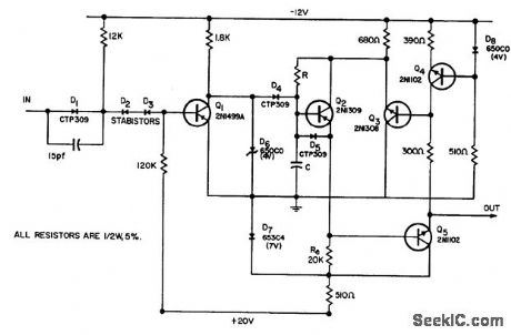
Balanced_modulator_for_SSB_operation
Published:2009/7/23 22:41:00 Author:Jessie
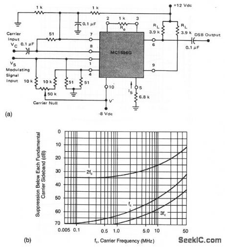
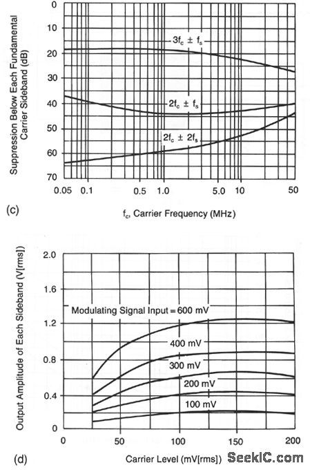
This circuit shows an MC1596 operating as a balanced modulator with +12-V and -8-V supplies. Recommended input signal levels are 60 mV (rms) for the carrier and 300 mV (rms) for the maximum modulating signal. Figures 2-42B and 2-42C show the suppression of carrier and sidebands, respectively. Figure 2-42D shows the sideband output levels. (View)
View full Circuit Diagram | Comments | Reading(779)
5_HOUR_RAMP
Published:2009/7/23 22:41:00 Author:Jessie
Switches S1 and S2 give ramp periods of 100 to 4,000 sec. Changing C to 10 mid increases period to 20,000 sec. For 5-hour period, C must be 10-mfd low-leakage capacitor. R1 calibrates ramp amp litude and R2 calibrates period.-R. Chapman Period of Sawtooth Ramp Extends to 5 Hours, Electronics, 39:13, p 78. (View)
View full Circuit Diagram | Comments | Reading(511)
WATCH_TIMER
Published:2009/7/23 22:41:00 Author:Jessie
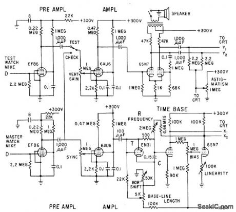
Simple time base, with high linearity, is achieved by two-stage d-c amplifier having unity gain, back-coupled to R.C integrator. Time-base reference, synchronized with master clock, can check accuracy of any timing device.-S. T. Kiewied, Watch Timer with Precise Time Base, Electronics, 31:51, p 84-85. (View)
View full Circuit Diagram | Comments | Reading(677)
Capacitance_multiplier
Published:2009/7/23 22:40:00 Author:Jessie

This circuit appears as a capacitance to the input. (View)
View full Circuit Diagram | Comments | Reading(0)
ALL_WAVEFORM_GE_N_ERATOR
Published:2009/7/23 22:40:00 Author:Jessie
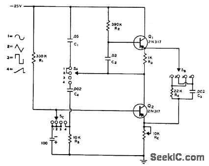
Two-transistor circuit with function switch provides choice of four different waveforms: sine, triangular, square, and sawtooth. Frequency is around 450 cps.-Transistorized All-Waveform Generator, Electronics Circuit Design Handbook, Mactier Pub. Corp., N.Y., 1965, p 168. (View)
View full Circuit Diagram | Comments | Reading(676)
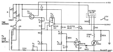
DUAL_POLARITY_START_STOP_CONTROL
Published:2009/7/23 22:40:00 Author:Jessie

Switches connect relay coils either to positive bus or to ground, so timer can be controlled by either positive or negative pulses. Additional transistor, used in place of relay, pro vides stop switching.Q3 forms damping cir. cult for use where stop pulse duration is too short.-F. W. Kear, Tests Show Control is Key to Timer Accuracy, Electronics, 33:27, p 62. (View)
View full Circuit Diagram | Comments | Reading(601)
Positive_negative_dual_tracking_power_supply
Published:2009/7/23 22:40:00 Author:Jessie
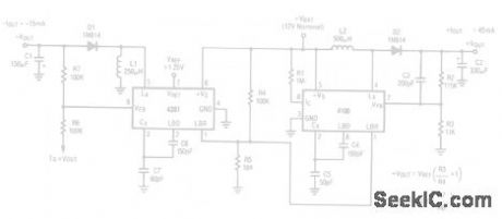
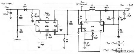
This circuit uses the 4190 as a step-up regulator and the 4391 as an inverter. The supply is capable of delivering +45 mA (15 mA with regulation) until the battery decays below 5.0V. Output voltage ripple is under 100 mVpp at ± 15-V output. (View)
View full Circuit Diagram | Comments | Reading(710)
WIDE_RANGE_LINEAR_BOOTSTRAP_TIME_BASE
Published:2009/7/23 22:39:00 Author:Jessie
Delivers highly linear ramps at repetition roles up to 5 Mc, for input pulses from 0.1 microsec to several seconds wide. Nonlinearity is 5% for slow ramps, and improves to 0.05% for fast ramp. Measures pulse width accurately when used in combination with voltage comparator. Can also be used for sampling and for testing amplitude response of linear amplifiers.-T. Mollinga, A Wide-Range, Linear Time Base, EEE, 10:8, p 56-59. (View)
View full Circuit Diagram | Comments | Reading(629)
VHF_frequency_synthesizer
Published:2009/7/23 22:39:00 Author:Jessie
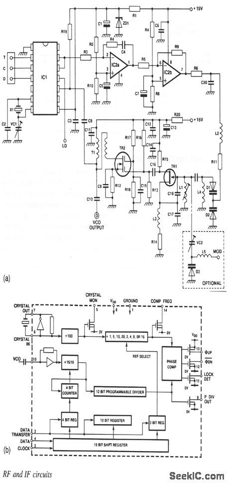
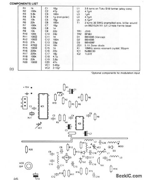
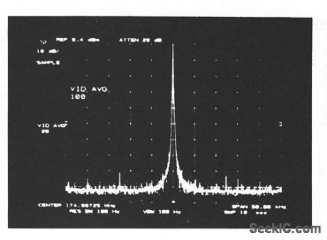
The NF88C30 shown in this circuit contains all the logic required for a high-band VHF PLL synthesizer. Figure 2-41 shows the internal circuits or the chip. The components list is shown in Fig. 2-41 C. As shown in the PC-board layout of Fig. 2-41D, the ground place is split between the VCO and synthesizer-control sections, with dc connections made via narrow tracks on either side of the board.This construction prevents synthesizer currents from causing spurious sidebands in the VCO output. The VCO can be modulated externally by adding L5, D3, and VC2. The output spectrum is shown in Fig. 2-41E. The output power is 9.4 dBm into 50Ω, with a frequency swing of about 10 MHz (from 170 to 1 80 MHz in this case). (View)
View full Circuit Diagram | Comments | Reading(1144)
Microprocessor_interface_for_free_running_A_D
Published:2009/7/23 22:39:00 Author:Jessie
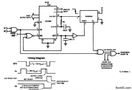
This circuit provides for asynchronous reads of analog data to an 8-bit microprocessor. The CD4024BC ripple counter generates a READY signal to the microprocessor that prevents a READ during a data update. The output data latches are updated one A/D-clock period before the INTR falls low, and the free-running conversion time is always 72 clock periods long. To start the A/D converter, a logic low must be applied to the SYSTEM RESET. The timing diagram shows relationships of the INTR, READY, and RDsignals. (View)
View full Circuit Diagram | Comments | Reading(625)
TV_REMOTE_CONTROL_TESTER
Published:2009/7/23 22:39:00 Author:Jessie

Grid-controlled mvbr has sweep of 0 to 7 kc, with center frequency adjustable from 36 to 44 kc. Maximum output is 85 v peak-to-peak. Neontube sweep generator operates at 1, 6, and 22 cps. Used for testing ultrasonic remote controls.-G. Row, Sweep Generator Tests Ultrasonic Remote Controls, Electronics, 34:47, p 64-66.
(View)
View full Circuit Diagram | Comments | Reading(579)
| Pages:1101/2234 At 2011011102110311041105110611071108110911101111111211131114111511161117111811191120Under 20 |
Circuit Categories
power supply circuit
Amplifier Circuit
Basic Circuit
LED and Light Circuit
Sensor Circuit
Signal Processing
Electrical Equipment Circuit
Control Circuit
Remote Control Circuit
A/D-D/A Converter Circuit
Audio Circuit
Measuring and Test Circuit
Communication Circuit
Computer-Related Circuit
555 Circuit
Automotive Circuit
Repairing Circuit