
Circuit Diagram
Index 1114
VOICE_BANDPASS
Published:2009/7/3 4:14:00 Author:May

Used between 8-ohm output of communication receiver and 8-ohm Loud-speaker or low-impedance phones, to suppress Continuous Random Unwanted Disturbances on voice transmissions. Passband is 355 to 2530 Hz at 3-dB points. L1 and L3 are 4a-mH toroids.L2 is 88-mH toroid with 94 turns removed. T1 and T2 are 88-mH toroids with 100 turns No.28 enamel wound over original winding of each for primary.-R. M. Myers, The SSB Crud-O-Ject, QST, May 1974, p 23-25 and 56 (View)
View full Circuit Diagram | Comments | Reading(1295)
Negative_step_up_dc_dc_converter
Published:2009/7/23 23:51:00 Author:Jessie

Figure 7-22 shows the MAX724 connected to provide a -15-V output with a -5-V to -15-V input. See Figs. 7-18 and 7-19 for pin configurations, and Fig. 7-20 for component suppliers. MAXIM EVALUATION KIT DATA Book, 1994, P. 3-138. (View)
View full Circuit Diagram | Comments | Reading(747)
5_A_positive_adjustable_current_regulator
Published:2009/7/23 23:51:00 Author:Jessie

This circuit uses the LAS19U voltage-regulator IC (Fig. 7-47) as an adjustable-current regulator. Characteristics are shown in Fig. 7-46B, 7-46C and 7-46D. (View)
View full Circuit Diagram | Comments | Reading(917)
2955_MHz_HIGH_PASS
Published:2009/7/3 4:13:00 Author:May

Used in offset frequency-measuring system for amateur-band signals. Nine-section Chebvshev high-pass filter with 1-dB passband ripple attenuates undesired 2.045-2.245 MHz image 16 dB while selecting desired 2.955-3.155 MHz signal. Filterhas sharper cutoff characteristic, for given num ber of sections, than Butterworth or image parameter designs.-J. Walker, Accurate Frequency Measurement of Received Signals, Ham Radio, Oct. 1973, p 38-55. (View)
View full Circuit Diagram | Comments | Reading(653)
LOW_PASS_WITH_425_MHz_CUTOFF
Published:2009/7/3 4:12:00 Author:May

Designed for insertion in antenna coax of amateur radio station up to 1 kW, to cure TVI Problems.Provides 60-dB attenuation on channel 2. Filter uses mderived terminating half-sections at each end, with two constant-K midsections.End sections are tuned either to channel 2 (55 MHz) or channel3(61 MHz), Article covers construction and tune-up.-N. Johnson, High-Frequency Lowpass Filter, Ham Radio, March 1975, p 24-27. (View)
View full Circuit Diagram | Comments | Reading(623)
LOW_POWER_DRIVER
Published:2009/7/23 23:34:00 Author:Jessie
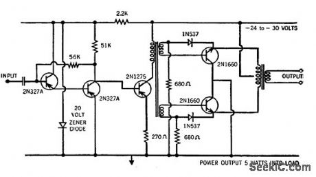
Pair of high-voltage, high-gain silicon power transistors gives 5W output from -55 to +125℃ when driven by 250-mw 2N1275 transistor.-New High Volt-age, High Gain Transistors (Raytheon Ad), Electronics, 33:35, p 42. (View)
View full Circuit Diagram | Comments | Reading(655)
Basic_function_test
Published:2009/7/23 23:51:00 Author:Jessie
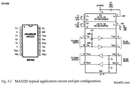
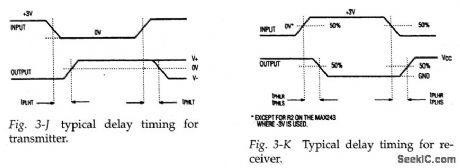
Figure 3-I shows the bypical application circuit and pin configuration for the MAX220.This EIA-232D interface(driver/receiver) operates from 5V,and is also suited for use in systems designed to V.28/V.24 specifications. The basic function is tested by comparing waveforms at the input and output of all four channels. In theory, the waveforms should be identical, except for possible delay. Figures 3-J and 3-K show typical delay timing for both the transmitter and receiver. For reference, the MAX220 receiver delay is 0.6μs (typical) and 3μs (maximum). The trans-mitter delay is 4μs (typical) and 10μs (maximum).
If one or more (but not all) of the four channels shows no output, severe dis-tortion, or excessive delay, the IC is suspect. If all four channels are defective, and +5 V is at pin 16, check the four capadtors (C1 through C4). These capadtors are used in the voltage-doubling (charge pump) and voltage-inverting functions within the IC. If the capacitors are good, and +5-V power is applied, but any or all of the channels are defective, suspqct the IC. (View)
View full Circuit Diagram | Comments | Reading(957)
BATTERY_CHARGER_OPERATES_ON_SINGLE_SOLAR_CELL
Published:2009/7/3 4:11:00 Author:May

The circuit charges a 9-V battery at about 30 mA per input ampere at 0.4 V. U1, a quad Schmitt trigger, operate as an astable multivibrator to drive push-pull TMOS devices Q1 and Q2. Power for U1 is derived from the 9-V battery via D4; power for Q1 and Q2 is supplied by the solar cell. The multivibrator frequency, determined by R2-C1, is set to 180 Hz for maximum efficiency from a 6.3-V filament transformer, T1. The secondary of the transformer is applied to a full wave bridge rectifier, D1, which is connected to the batteries being charged. The small Ni-Cad battery is a fail-safe excitation supply to allow the system to recover if the 9-V battery becomes fully discharged.A CdS photocell shuts off the oscillator in darkness to preserve the fail-safe battery during shipping and storage, or prolonged darkness (View)
View full Circuit Diagram | Comments | Reading(1069)
DIODE_SWITCHED_CRYSTALS
Published:2009/7/3 4:11:00 Author:May

1N458 diodes switch crystals in pairs to provide two different degrees of selectivity for 455-kHz IF filter, For 500-Hz bandwidth in amateur communication receiver, spacing between crystal frequencies should be 300 Hz, which is obtained with 455.150 kHz for Y1A and 454.850 kHz for Y1B.Provides adequate CW selectivity for transceiver having good SSB filter.-J. J. Schultz, Economical Diode-Switched Crystal Filters, CQ, July 1978, p 33-35 and 91.
(View)
View full Circuit Diagram | Comments | Reading(735)
COMMON_PLATE_TRIODE_MIXER
Published:2009/7/23 23:34:00 Author:Jessie
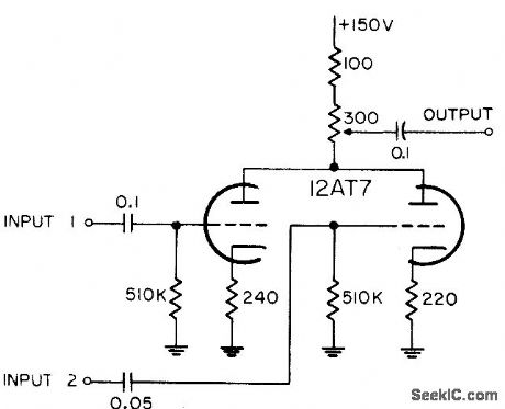
Has two inputs, for combining mixed markers and radar video. Cathode resistors are unby-passed, for gain stabilization.-NBS, Handbook Preferred Circuits Navy Aeronautical Electronic Equipment, Vol. 1, Electron Tube Circuits, 1963, p N4-3. (View)
View full Circuit Diagram | Comments | Reading(576)
STEREO_DECODER_
Published:2009/7/3 4:11:00 Author:May

Single Sprague ULN-2122A IC is driven by composite signal derived at output of standard FM detector, to give original left- and right-channel audio signals for driving audio amplifiers of FM stereo receiver.-E. M. Noll, Linear IC Principles, Experiments, and Proiects, Howard W. Sams, Indianapolis, IN, 1974, p 263-266. (View)
View full Circuit Diagram | Comments | Reading(853)
PROGRAMMER_FOR_SIGNETICS_8223
Published:2009/7/3 4:10:00 Author:May


Bounceless switch U1 triggers mono MVBR U2, both operating at 7 V above ground. When Q1is saturated by pulse from U2, it applies 250-ms 12.5-V programming pulse to VCC terminal (pin 16) of memory chip and opens fuse at previously addressed bit to make it logic 1. Separate regulators are required for 7 V and 12.5 V. Used with alphameric display having five 7-segment digits in circuit serving as function/units indicator for interval timericounter, where it forms simulation of abbreviations for time and frequency units. Articlegives step-by-step instructions for mistake-free operation of programmer.-J. W. Springer, Function/Units Indicator Using LED Displays, Ham Radio, March 1977, p 58-63. (View)
View full Circuit Diagram | Comments | Reading(890)
FOUR_CRYSTAL_FILTER
Published:2009/7/3 4:10:00 Author:May

Uses two matched sets of crystals, with each pair having maximum frequency difference of 25 Hz.Transistors serve as input and output isolating stages. Each matched pair, such as A-A', should be from same manufacturer and have same nominal parallel capacitance for circuit, same activity, and same resonant frequency within 25 Hz. Artide gives detailed instructions for grinding crystal to increase resonant frequency when necessary for matching. Use frequency counter for checking frequency. Values given in circuit are for 5.645-MHz crystal filter with -6dB band-pass of L82 kHz and insertion loss of about 5 dB. Crystals used are 5.644410 MHz and 5.644416 MHz for A and A', and 5.645627 MHz and 5.645641 MHz for B and B'. Coil has 7 + 7 turns No.28 enamel bifilar wound on 10.7-MHz IF transformer having 2.4-mm slug diameter. C, is 39 to 47 pF.-J. Perolo, Practical Considera-tions in Crystal-Filter Design, Ham Radio. Nov.1976, p 34-38.
(View)
View full Circuit Diagram | Comments | Reading(1151)
2_A_positive_fixed_voltage_regulator
Published:2009/7/23 23:34:00 Author:Jessie

The LAS1600 series voltage regulators are ICs containing all elements necessary for linear regulation (safe-area protection, thermal overload, current limiting, as shown in Figure 7-37C). Figure 7-32B shows the output voltage and tolerance for the various LAS1600 part numbers. Figure 7-37D shows the absolute maximum ratings. (View)
View full Circuit Diagram | Comments | Reading(630)
PREFERRED_PULSE_EMITTER_FOLLOWER
Published:2009/7/23 23:33:00 Author:Jessie

Two-stage cascaded emitter-follower is intended primarily as video line driver for positive pulses. Will drive load impedances as low as 50 ohms. Input impedance is about 80000 ohms in parallel with 25 pf. May be modified for negative inputs by replacing Q1 and Q2 with complementary pnp types and reversing polarity of collector supply. Voltage amplification is 0.975 and power gain is 30 db.-NBS, Handbook Preferred Circuits Navy Aeronautical Electronic Equipment, Vol. II, Semiconductor Device Circuits, 1962, PSC 21 (originally PC 221) p 21-2. (View)
View full Circuit Diagram | Comments | Reading(1337)
2125_Hz_LOW_PASS
Published:2009/7/3 4:09:00 Author:May

Used with AFSK keyer to convert 2125-Hz square wave to sine wave by removing third and fifth harmonics. All three coils are toroids, with its two windings in series for 88 mH and in parallel for 23 mH.-L.J.Fox,Dodge That Hurricane!,73 Magazine,Jan. 1978, p 62-69. (View)
View full Circuit Diagram | Comments | Reading(607)
DIODE_SWITCHED_FOUR_CRYSTAL_IF_FILTER
Published:2009/7/3 4:08:00 Author:May

Appiication of 9-12 VDC to control points A or B gives choice of two different selectivities for IF amplifier in amateur communication receiver.For 500-Hz bandwidth at 455 kHz, frequencies of crystals in use should be 300 Hz apart for CW, 1.8 kHz apart for 2.7-kHz SSB bandwidth, and 1.25 kHz apart for 2.1-kHz SSB bandwidth. Article gives design graphs.-J. J. Schultz, Economical Diode-Switched Crystal Filters, CQ, July 1978, p 33-35 and 91. (View)
View full Circuit Diagram | Comments | Reading(754)
Step_up_PWM_regulators
Published:2009/7/23 23:33:00 Author:Jessie
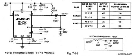
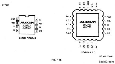
Figure 7-14 shows the MAX732 and MAX733 connected as step-up PWM (pulse-width modulation) regulators. Typical efficiency for the MAX731 is 82% to 87%, with 85% to 95% for the MAX733. Figure 7-15 shows the pin configurations. MAXIM HIGH-RELIAsILITY DATA BOOK, 1993, P. 4-65. (View)
View full Circuit Diagram | Comments | Reading(643)
WIND_POWERED_BATTERY_CHARGER
Published:2009/7/3 4:06:00 Author:May
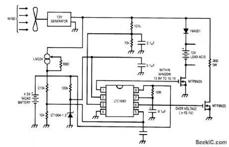
The dc motor is used as a generator with the voltage output being proportional to its rpm. The LTC1042 monitors the voltage output and provides the following control functions.
1. If generator voltage output is below 13.8 V, the control circuit is active and the Ni-Cad battery is charging through the LM334 current source. The lead acid battery is not being chirged.2. If the generator voltage output is between 13.8 V and 15.1 V, the 12 V lead acid battery is being charged at about 1 amp/hour rate (limited by the power FET).3. If generator voltage exceeds 15.1 V (a condition caused by excessive wind speed or 12 V battery being fully charged) then a fixed load is connected limiting the generatorrpm to prevent damage.
This charger can be used as a remote source of power where wind energy is plentiful such as on sailboats or remote radio repeater sites. Unlike solar powered panels, this system will function in bad weather and at night. (View)
View full Circuit Diagram | Comments | Reading(3905)
PROM_WITH_LED_DlSPLAY
Published:2009/7/3 4:05:00 Author:May

Developed for use in debugging small microprocessor systems.Uses LEDs in place of diodes as OR gates of 8 x 12-bit diode matrix memory which displays memory-cell content when word is addressed during execution of a program. Monitor switches can be used fordata displaywhen program is inserted. System was built to debug lntersil IM6100 μP. Since voltage output of diode array is too small for direct input to MOS circuit,7408 gates are used to boost high-level output.Article gives instructions for use of display.-K.S. Hojberg, Light-Emitting Memory Aids μP Debugging, EDN Magazine, May 5, 1977, p 107.
(View)
View full Circuit Diagram | Comments | Reading(643)
| Pages:1114/2234 At 2011011102110311041105110611071108110911101111111211131114111511161117111811191120Under 20 |
Circuit Categories
power supply circuit
Amplifier Circuit
Basic Circuit
LED and Light Circuit
Sensor Circuit
Signal Processing
Electrical Equipment Circuit
Control Circuit
Remote Control Circuit
A/D-D/A Converter Circuit
Audio Circuit
Measuring and Test Circuit
Communication Circuit
Computer-Related Circuit
555 Circuit
Automotive Circuit
Repairing Circuit