
Circuit Diagram
Index 1102
Simulated_inductor
Published:2009/7/23 22:39:00 Author:Jessie

This circuit appears as an inductor to the input. The inductance is set by selection of R1, R2, and C1. (View)
View full Circuit Diagram | Comments | Reading(2522)
Product_detector_for_SSB_operation
Published:2009/7/23 22:43:00 Author:Jessie

This circuit shows an MC1596 operating as a product detector with a single +12-V supply. The circuit can operate up to 100MHz. When operating in an SSB receiver with 50-Ω input impedance and an 0.5-μV RF input, 12-dB overall gain is required between antenna and the MC1596. Dual outputs (pins 6 and 9) can be used to drive the receiver audio amplifiers, and an AGC circuit, if desired. (View)
View full Circuit Diagram | Comments | Reading(2049)
INTERVALOMETER
Published:2009/7/23 22:43:00 Author:Jessie
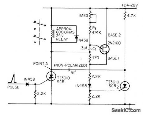
Operates at end of pre determined period to produce second pre determined time period in range of 5 to 10 sec. Developed for medical electronic re search. Standby current is only 5 mc.-E. L. Dewig, Inexpensive UJT-SCR Intervalometer, EEE, 14:7, p 104. (View)
View full Circuit Diagram | Comments | Reading(1123)
High_power_step_down_voltage_regulator
Published:2009/7/23 22:43:00 Author:Jessie
This circuit shows a stop-down regulator for loads up to 5 W. Notice that a minimum load of at least 1 mA must be connected when the circuit is energized. (View)
View full Circuit Diagram | Comments | Reading(713)
TRIGGERED_SAWTOOTH
Published:2009/7/23 22:43:00 Author:Jessie
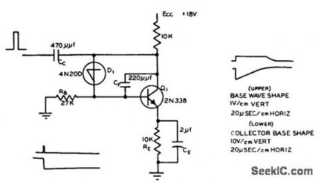
Uses Shockley four-layer diode and transistorized integrating circuit. Ramp starts with quick drop, then rises back to steady-state condition. Pulse width is 0.2 microsec at 400 pps.-Triggered Sawtooth Generator, Electronic Circuit Design Handbook, Mactier Pug. Corp., N.Y., 1965, p 169. (View)
View full Circuit Diagram | Comments | Reading(731)
ENCODER_COUNTER
Published:2009/7/23 22:43:00 Author:Jessie

Counter, limit trigger, and blocking oscillator ore given for encoder used for storing and reading out elapsed time between consecutive randomly occurring events. First 23 counters are identical.-R. J. Kelso and J. C. Groce, Encoder Measures Random Event Time Intervals, Electronics, 32:12, p 48-51. (View)
View full Circuit Diagram | Comments | Reading(1098)
Amplitude_modulator
Published:2009/7/23 22:42:00 Author:Jessie

This circuit shows an MC1596 operating as an amplitude modulator with +12,- and -8-V supplies. The circuit provides modulation at any percentage from zero to greater than 100%. (View)
View full Circuit Diagram | Comments | Reading(0)
UNIJUNCTION_SAWTOOTH
Published:2009/7/23 22:42:00 Author:Jessie
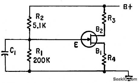
Uses ZJ14 unijunction transistor. R1 represents input impedance of conventional emitter-follower having nominal 5,000.ohm impedance in emitter circuit. R3 is 3K and R4 is 330 ohms.-M. Rosen, Subaudio Swept Signal Generator, Electronics, 33:17, p 67-68. (View)
View full Circuit Diagram | Comments | Reading(677)
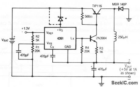
Isolated_switching_regulator_for_LAN
Published:2009/7/23 22:42:00 Author:Jessie

This power supply is suitable for local area networks, such as EthernetTM or CheapernetTM. Figure 6-65B tabulates the design specifications, based on IEEE 802.3 and ECMA 200-V. (View)
View full Circuit Diagram | Comments | Reading(555)
Basic_inverting_voltage_regulator
Published:2009/7/23 22:42:00 Author:Jessie
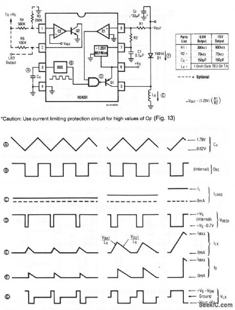
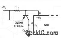
Figures 4-12A and 4-12B show a basic inverting voltage regulator and waveforms, respectively. The outputs are -5 or -15 V, using the values shown.Other outputs can be selected by changing R1 and R2. It may be necessary to change other circuit values. If high values of CF are used, a current-limiting protection circuit (Fig. 4- 12C) might be required. (View)
View full Circuit Diagram | Comments | Reading(657)
SING_AROUND_COUNTER_CONTROL
Published:2009/7/23 22:42:00 Author:Jessie

Timer start-pulse generator is fast series-transistor coincidence circuit. Slop-gate generator is one-shot mvbr that prevents 1N97A diode from passing blocking oscillator negative sync pulse until mvbr fires. Used to count number of sing-around cycles and measure total time in system for measuring ultrasonic velocity in liquids and solids.-R. L. Forgacs, Precision Ultrasonic Velocity Measurements, Electronics, 33:47, p 98-100. (View)
View full Circuit Diagram | Comments | Reading(623)
Linear_thermometer
Published:2009/7/23 22:42:00 Author:Jessie

This circuit uses both sections of an LT1002 to form a simple (but accurate) thermometer. To calibrate, substitute a precision decade box (General Radio 1432-K) for the sensors. Set the box to the 0°C value (1000.0Ω) and adjust the offset trim for a 0.000-V output. Then, set the decade box for a 35°C output (1138.7 Ω) and adjust the gain trim for a 3.500-V output reading. Finally, set the box to 1392.6 Ω (100.00°C) and trim the linearity adjustment. Repeat the sequence until all three points are fixed. The total error over the entire range will be within ±0.025°C. (View)
View full Circuit Diagram | Comments | Reading(679)
13_SEC_TIMER
Published:2009/7/23 22:42:00 Author:Jessie

Two silicon transistors start timing action when 10-millisec start pulse closes reed relay K1, making output transistor Q1 conductive for 13 sec. Timing period can be shortened by applying 36-millisec pulse to K2.-H. W. Hines and L. C. Radzik, Electronic Timer Provides Long Delay, Electronics, 37:17, p 63. (View)
View full Circuit Diagram | Comments | Reading(726)
TELEPRINIER_CHARACTER_COUNTER
Published:2009/7/23 22:27:00 Author:Jessie
Simple circuit switches on timer dock only when teleprinter keying impulses are present, to give indication of traffic volume, low, and routing.-R. E. Pafenberg, Character Counter Aids Teletypewriter Routing, Electronics, 34:17, p 120-121. (View)
View full Circuit Diagram | Comments | Reading(763)
Single_balanced_mixer
Published:2009/7/23 22:27:00 Author:Jessie
This circuit shows an SL2365 transistor array (Fig.2-35B) connected as a balance mixer, with a gain of 13 dB, a third-order incercept of -13 dB, and a noise figure of 10 dB. (View)
View full Circuit Diagram | Comments | Reading(793)
SPDT_switches_MAX335
Published:2009/7/23 22:26:00 Author:Jessie


To use the MAX as a single-pole double-throw (SPDT) switch, tie COM0 to N01 so that N00 and COM1 are now inputs and COM0/N01 is the common output. Up to four SPDT switches can be made from each MAX335. Multiples of four or more can be made by daisy-chaining the ICs. Figure 2-33 shows the serial input control for SPDT switch operation. Again, CS is held low to clock in pulses, and pulled high to update; CS is also held low to shift pulses, then pulled high to update, etc. (View)
View full Circuit Diagram | Comments | Reading(638)
100__to_300_MHz_frequency_tripler
Published:2009/7/23 22:26:00 Author:Jessie
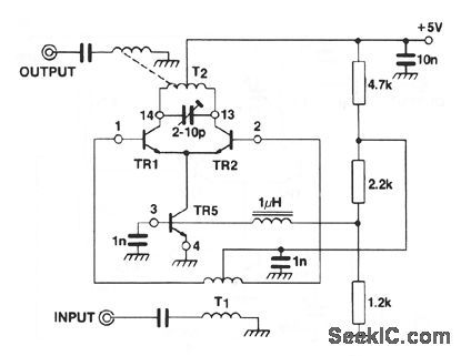
This circuit shows an SL2365 transistor array (Fig. 2-35B) connected as a frequency tripler, with a gain of -40 dB, an input-frequency rejection of 30 dB, and second-harmonic rejection of 28 dB. (View)
View full Circuit Diagram | Comments | Reading(752)
CONSTANT_CURRENT_GENERATOR
Published:2009/7/23 22:25:00 Author:Jessie
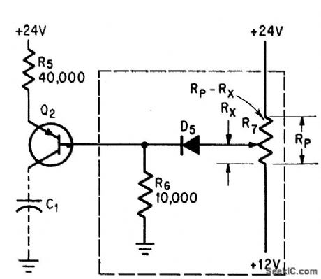
Insures that voltage across charging capacitor of unijunction-transistor timer increases linearly with time. Maximum charging current is about 0.3 mo with 2N2605 for C12 and 1N643 for D5. R7 is 1,000-ohm potentiometer.-A. A. Lampell, Off-the-Shelf Integrated Circuits for Versatile and Accurate Timer, Electronics, 38:25, p 70-73. (View)
View full Circuit Diagram | Comments | Reading(3)
150__to_300_MHz_frequency_doubler
Published:2009/7/23 22:25:00 Author:Jessie
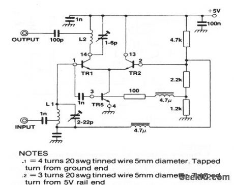
This circuit shows an SL2365 transistor array (Fig. 2-35B) connected as a frequency doubler, with a gain of +1 dB for a -20 dB input, and an input-frequency rejection of 18 dB. (View)
View full Circuit Diagram | Comments | Reading(774)
HIGH_LINEARITY_SAWTOOTH
Published:2009/7/23 22:25:00 Author:Jessie
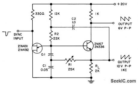
Requires only single positive supply. Npn transistor serves as output buffer amplifier, while R2 and C2 in bootstrap circuit improve linearity of saw tooth. R1 and C1 act as integrating network to provide second. order compensation for nonlinearity of waveform.- Transistor Manual, Seventh Edition, General Electric Co., 1964, p 319. (View)
View full Circuit Diagram | Comments | Reading(917)
| Pages:1102/2234 At 2011011102110311041105110611071108110911101111111211131114111511161117111811191120Under 20 |
Circuit Categories
power supply circuit
Amplifier Circuit
Basic Circuit
LED and Light Circuit
Sensor Circuit
Signal Processing
Electrical Equipment Circuit
Control Circuit
Remote Control Circuit
A/D-D/A Converter Circuit
Audio Circuit
Measuring and Test Circuit
Communication Circuit
Computer-Related Circuit
555 Circuit
Automotive Circuit
Repairing Circuit