
Circuit Diagram
Index 1119
COMPLETE_2_W_SERVO_AMPLIFIER
Published:2009/7/23 23:40:00 Author:Jessie
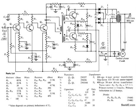
Includes direct-coupled preamplifier and driver stages, with considerable d-c feedback to stabilize bias conditions. Voltage gain of amplifier with feedback loop closed is 10,000. Overall efficiency is 50%. Input impedance is 10,000 ohms and output impedance is 150 ohms.-Texas Instruments Inc., Transistor Circuit Design, McGraw-Hill, N.Y., 1963, p 247. (View)
View full Circuit Diagram | Comments | Reading(1005)
15_A_dual_adjustable_voltage_regulator
Published:2009/7/23 23:40:00 Author:Jessie
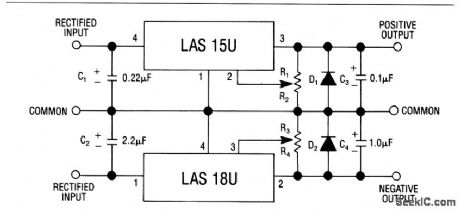
This circuit uses an LAS15U (Fig. 7-33) and an LAS18U (Fig. 7-43) to form a dual, adjustable, voltage regulator with outputs from +1.2 to +32 V and -2.6 to -30 V. The LA515U characteristics are shown in Fig. 7-32B, C and D, The LAS18U characteristics are shown in Fig. 7-42B, 7-42C, and 7-42D. (View)
View full Circuit Diagram | Comments | Reading(982)
DELAYED_ACTION_WINDSHIELD_WIPER_CONTROL
Published:2009/7/3 3:17:00 Author:May

View full Circuit Diagram | Comments | Reading(572)
400_CPS_SERVO_AMPLIFIER_SUPPRESSES_THIRD_HARMONIC
Published:2009/7/23 23:39:00 Author:Jessie
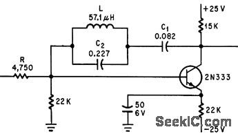
Single-transistor operational amplifier for 400aps servosystems gives accurate 90-deg phase shift at carrier frequency and open-loop gain of 34 db. Circuit resonance at 1,200 cps keeps third harmonic 20 db down.-M. Schmidt, Operational Amplifier Suppresses Third Harmonic, Electronics, 35:13, p 74. (View)
View full Circuit Diagram | Comments | Reading(588)
±15_V_CHOPPER_AMPLIFIER
Published:2009/7/3 3:17:00 Author:May
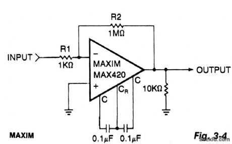
This simple circuit is a gain-of-1000 inverting amplifier. It will amplify submillivolt signals up to signal levels suitable for further processing. In almost all system applications, it is best to use as much gain as possible in the MAX420, thus minimizing the effects of later-stage offsets. For exam-ple, if circuitry following the MAX420 has an offset of 5 mV, the additional offset referred back to the MAX420 input (gain = 1000) will be 5μV, doubling the system's offset error. (View)
View full Circuit Diagram | Comments | Reading(581)
2_A_positive_adjustable_current_regulator
Published:2009/7/23 23:39:00 Author:Jessie
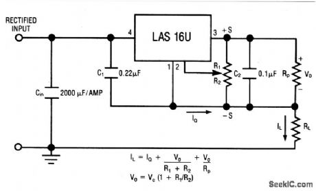
This circuit uses the LAS16U voltage-regulator IC (Fig. 7-38) as an adjustable-current regulator. Characteristics are shown in Fig. 7-37B, 7-37C, and 7-37D. (View)
View full Circuit Diagram | Comments | Reading(557)
COMBINED_NEGATIVE_POSITIVE_FEEDBACK
Published:2009/7/23 23:39:00 Author:Jessie
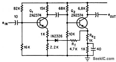
Two-stage common-emitter amplifier permits use of positive feedback to Rf along with negative feedback, to give stability factor of 5 and overall gain of 47 db with input impedance of 10,000 ohms for small-pulse amp lification in servo system.-N. A. Wade, Combined Feedback Stabilizes Amplifier, Electronics, 37:15, p 76. (View)
View full Circuit Diagram | Comments | Reading(2210)
FSK_DEMODULATOR_FOR_EKG_RELAY
Published:2009/7/3 3:15:00 Author:May
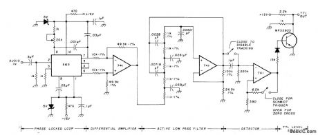
Used at receiving end of satellite system for relaying EKGs, to convert received audio FSK signal to TTL level-shifting output from which original EKG can be obtained. Phase-locked loop tracks input signal frequency and feeds appropriate error signal through differential amplifier to five-pole Butterworth low-pass filter having 1500-Hz cutoff. DC offset is removed by capa-itor coupling, for use in zero-crossing detector or Schmitt-trigger detector. Signal is next converted into TTL-compatible level. Recorded output could not be distinguished from original EKG by doctors.-D. Nelson, Medical Data Relay via Oscar Satellite, Ham Fladio, April 1977, p67-73. (View)
View full Circuit Diagram | Comments | Reading(1152)
BAR_GRAPH_VOLTMETER
Published:2009/7/3 3:13:00 Author:May

This display uses ten LED's to display a voltage range from 10.5 to 15 volts. Each LED represents a 0.5-volt step in voltage. The heart of the circuit is the LM-3914 dot/bar display driver. Trimmer potentiometer R5 is adjusted so that 7.5 volts is applied to the top side of the divider. Resistor R7 and diodes D2 through D5 clamp the voltage applied to the LED's to about 3 volts. A lowpass filter made up of L1 and C2 guards against voltage spikes. Diode D1 is used to protect against reverse voltage in case the voltmeter is hooked up backward. (View)
View full Circuit Diagram | Comments | Reading(2443)
DC_MOTOR_SPEED_CONTROL
Published:2009/7/3 3:11:00 Author:May

Power op amps provide accurate speed control for dc motors. The circuit provides bidirectional speed control. The amplifiers' push-pull configuration ensures a full rail-to-rail voltage swing (minus the output stages' saturation drops) across the motor in either direction. The circuit uses a mechanically-coupled tachometer to provide speed-stabilizing feedback to the first amplifier section. The motor's speed and direction of rotation is set by adjusting the 10 k ohm potentiometer at the amplifier's noninverting input. The RFCF feedback network prevents oscillation by compensating for the inherent dynamic mechanical lag of the motor. Select the RFCF time constant to match the particular motor's characteristics. (View)
View full Circuit Diagram | Comments | Reading(0)
COMPRESSION_AMPLIFIER
Published:2009/7/23 23:39:00 Author:Jessie

Single transistor serves as compression amplifier having 50 db dynamic range, for nonsaturating amplification of widely ranging video signals. Provides minimum output of 1 v for 20 my input, but does not saturate with 6 v input. Circuit gain is minimum of 1 and maximum of 15. Two circuits are cascaded in actual application.-R. W. Cotterman, One Transistor, 50 Db Dynamic Range Compression Amplifier, EEE, 13:5, p 46. (View)
View full Circuit Diagram | Comments | Reading(1)
GARAGE_STOP_LIGHT
Published:2009/7/3 3:10:00 Author:May

Capacitor C1 is permanently connected across the 3-volt supply through 10 megohm resistor R1. The capacitor charges (relatively slowly) to 3 volts. The instant switch SW1 is closed, it connects the charged capacitor (C1) in series with C2 and R2. Capacitor C2 starts to charge, placing a positive-going voltage on the gate of the SCR and causing it to turn on. The two parallel-connected self-flashing bulbs I1 and I2 turn on. They flash and turn off the SCR and the circuit is off the switch and C1 can recharge. (View)
View full Circuit Diagram | Comments | Reading(652)
Amplifier_with_1000_V_output_28_V_supply
Published:2009/7/23 23:38:00 Author:Jessie
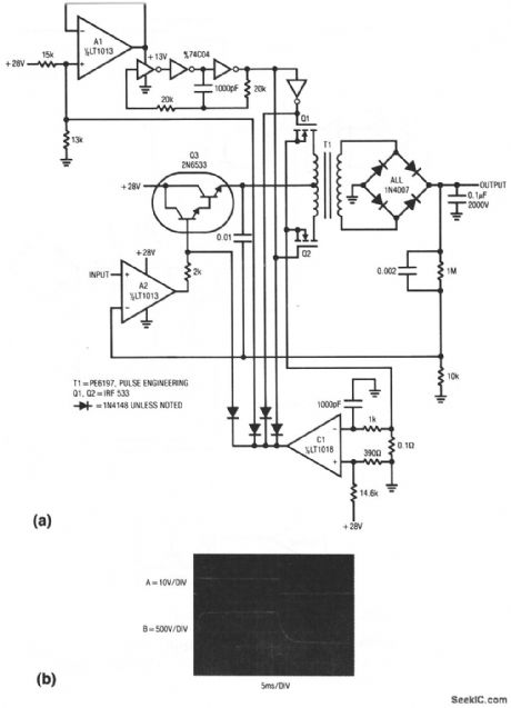
This unipolar-output amplifier swings 1000 V and supplies 15 W. The boost stage operates from a 28-V supply. Figure 1-15B shows the results with a±10-V input (trace A). Bandwidth is about 60 Hz. Danger! this circuit involves high voltages ! (View)
View full Circuit Diagram | Comments | Reading(514)
VARICAP_TUNER_
Published:2009/7/3 3:10:00 Author:May
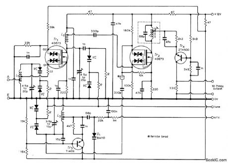
Uses silicon variable-capacitance diodes to provide voltage tuning over FM band of 87.5 to 108 MHz. Article covers construction and adjustment and gives circuit of stable noise-free regulated power supply that also provides required DC tuning voltage of 2 to 30 V. All six varicap diodes are Siemens BB103 of same color selection (all green or all blue).Resistors R can be any value between l00k and1 megohm.-L.Nelson-Jones,F.M.Tuner Design-Two Υears Later, Wireless World, June1973,p 271-275 (View)
View full Circuit Diagram | Comments | Reading(1938)
BACK_EMF_PM_MOTOR_SPEED_CONTROL
Published:2009/7/3 3:09:00 Author:May


The use of power MOSFETs allows a direct interface between logic and motor power, which permits circuit simplicity as well as high efficiency. This speed control circuit can be packaged on a 22-pin, double-sided, 3.5 x 4-in. pc board.
A 12 V control supply and a TRW BL11, 30V motor are used; with minor changes other motor and control voltages can be accommodated. For example, a single 24V rail could supply both control and motor voltages. Motor and control voltages are kept separate here because CMOS logic is used to start, stop, reverse and oscillate the motor with a variable delay between motor reversals.
Motor speed is established by potentiometer R2, which applies a corresponding dc voltage to the + input of comparator U1, whose output is then applied to TMOS device MTP8P08 (Q1). Zener diode D1 limits the drive to Q1. The output of Q1 drives the permanent magnet motor.
Back emf is obtained from the motor via the network consisting of R8, R9, R10, C2, C3 and D3; it is applied to-input of comparator U1. (View)
View full Circuit Diagram | Comments | Reading(1776)
EKG_TELEMETER
Published:2009/7/3 3:09:00 Author:May

Developed for experimentation or educational demonstrations in which audience listens to electrocardiograph signal voltage as fed through LM4250 opamp for modulating NE566 connected as VCO driving small loudspeaker. Acoustic output can be picked up by microphone for telemetry purposes if desired. Connection to patient can be made with standard adhesive monitoring electrodes or with small metal disks held on wfists with rubber bands. Tone shifts frequency with each pulse beat.-M. I. Leavey, lnexpensive EKG Encoder, 73 Magazine, Feb. 1978, p 20-23. (View)
View full Circuit Diagram | Comments | Reading(2289)
OVERVOLTAGE_PROTECTION_CIRCUIT_SCR_CROWBAR
Published:2009/7/3 3:08:00 Author:May

Circuit Notes
The silicon controllqd rectifier (SCR) is rated to handle at least the current of the power supply. It is connected in parallel across the 12 V dc output lines, but remains inert until a voltage appears at the gate terminal. This triggering voltage is supplied by the zener diode. At potentials less than 14 V the zener will not conduct current. But, at potentials greater than 14 Vdc the zener conducts and creates a voltage drop across the 330 ohm resistor that will fire the SCR. When the SCR turns on, the output lines of the power supply are shorted to ground. This will blow the primary fuse or bum out the transformer if there is no primary fuse. (View)
View full Circuit Diagram | Comments | Reading(1958)
CONSTANT_SPEED_MOTOR_CONTROL_USING_TACHOMETER_FEEDBACK_
Published:2009/7/3 3:07:00 Author:May
The generator output is rectified then filtered and applied between the positive supply voltage and the base of the detector transistor. This provides a negative voltage which reduces the base-voltage when the speed increases. In normal operation, if the tachometer voltage is less than desired, the detector transistor is turned on, then turns on Q2 which causes the timing capacitor for the unijunction transistor to charge quickly. As the tachometer output approaches the voltage desired, the base-emitter voltage is reduced to the point at which Q1 is almost cut off. Thereby, the collector current which charges the unijunction timing capacitor is reduced, causing that capacitor to charge slowly and trigger the thyristor later in the half cycle. In this manner, the average power to the motor is reduced until just enough power to maintain the desired motor speed is allowed to flow. (View)
View full Circuit Diagram | Comments | Reading(581)
MOTOR_SPEED_CONTROL_CIRCUIT
Published:2009/7/3 3:07:00 Author:May

A shortcoming of the above bi-directional proportional motor control circuit is that with the potentiometer in its center position the motor does not stop, but creeps due to the difficulty in setting the potentiometer for an exact 1:1 mark-space ratio from the flip-flop. This modified circuit uses a second potentiometer, ganged with the first used to inhibit drive to the motor near the center position. This potentiometer is connected between the supply lines and feeds a window comparator which in turn drives the inhibit input of the L293. (View)
View full Circuit Diagram | Comments | Reading(978)
SPEECH_SYNTHESIZER
Published:2009/7/3 3:05:00 Author:May


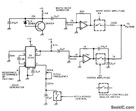
Based on analog simulation of vocal tract. Rush of air through vocal passages is simulated by white-noise generator, while action of larynx is simulated in lower branch of circuit. Article covers problems involved in achieving transitions from phoneme to phoneme, along with automatic emphasis of leading or terminating consonants and intonation of rhythm associated with importance or placement of word in speech. ASCII symbols are given for 33 phonemes generated in A1Cybernetic Systems model 1000 speech synthesizer, which uses circuit shown in combination with 10 active filters composed of 15 opamps, vocal excitation circuits, ASCII character decoders, and phoneme memories.-W. Atmar, The Time Has Come to Talk, Byte, Aug. 1976, p 26-30 and 32-33 (View)
View full Circuit Diagram | Comments | Reading(917)
| Pages:1119/2234 At 2011011102110311041105110611071108110911101111111211131114111511161117111811191120Under 20 |
Circuit Categories
power supply circuit
Amplifier Circuit
Basic Circuit
LED and Light Circuit
Sensor Circuit
Signal Processing
Electrical Equipment Circuit
Control Circuit
Remote Control Circuit
A/D-D/A Converter Circuit
Audio Circuit
Measuring and Test Circuit
Communication Circuit
Computer-Related Circuit
555 Circuit
Automotive Circuit
Repairing Circuit