
Circuit Diagram
Index 1109
Adjustable_linear_current_regulator
Published:2009/7/23 23:08:00 Author:Jessie
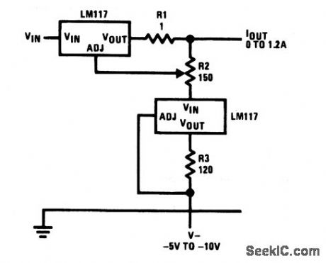
This circuit provides regulated current from 0 to 1.2A, as set by R2. (View)
View full Circuit Diagram | Comments | Reading(628)
TWO_PHOTOMULTIPLIER_SUBTRACTION_CIRCUIT
Published:2009/7/23 23:08:00 Author:Jessie
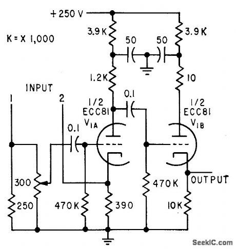
Flying-spot closed-circuit tv system compares two photographs and displays only differences between them, for automatic identification of variable stars. Both photo-multiplier signals are coupled to subtraction tube V1A. Difference signal is fed by cathode follower to video amplifier of 14-inch tv monitor.-J. Borgman, Using Tv Techniques in Astronomy, Electronics, 32:19, p 66-68. (View)
View full Circuit Diagram | Comments | Reading(738)
Adjustable_constant_voltage_constant_current_regulator
Published:2009/7/23 23:07:00 Author:Jessie
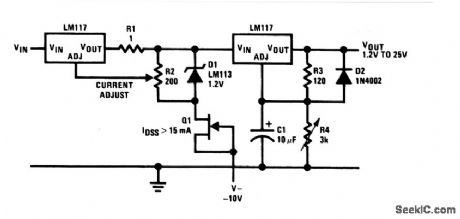
This circuit has a 1.2- to 15-V output range, set by R4. Current remains constant between 0 and 1.2 A, set by R2. (View)
View full Circuit Diagram | Comments | Reading(1281)
TWELVE_FREQUENCY_SERVO_TUNER
Published:2009/7/23 23:14:00 Author:Jessie
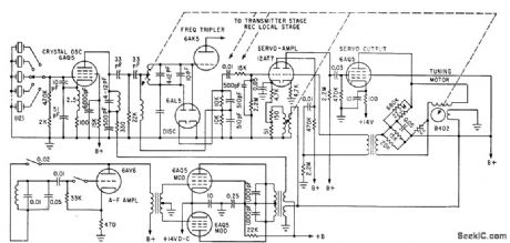
Negative feedback voltage proportional to servo speed is picked off winding of servomotor to improve stability in stopping at point of zero error voltage in output of 6AL5 frequency discriminator-K. Makino and T. Yamanaka, Servo-Tuned Transceiver for Airborne VHF Communications, Electronics, 35:1, p 82-85. (View)
View full Circuit Diagram | Comments | Reading(1152)
PUSH_PULL_CUPPER
Published:2009/7/23 23:13:00 Author:Jessie

Accepts balanced output of video preamp in microwave interferometer system and provides both linear and clipped outputs for oscilloscope.-H. L. Bunn Determining Electron Density and Distribution in Plasmas, Electronics, 34:14, p 71-75. (View)
View full Circuit Diagram | Comments | Reading(524)
Stereo_tone_control
Published:2009/7/23 23:13:00 Author:Jessie
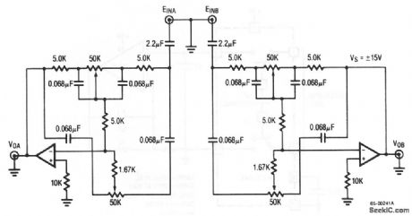
This circuit uses both halves of an RC4559 (Fig. 5-11B) (View)
View full Circuit Diagram | Comments | Reading(1807)
Multiple_on_card_regulators_with_single_control
Published:2009/7/23 23:13:00 Author:Jessie
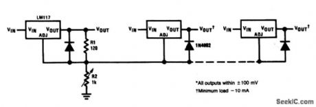

This circuit shows a method of adjusting several on-card regulators with a single control. All outputs should track within t 100 mV, with a minimum 10-mA load. (View)
View full Circuit Diagram | Comments | Reading(559)
TRANSDUCER_SCANNER_WITH_INDICATORS
Published:2009/7/23 23:12:00 Author:Jessie
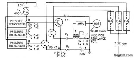
Transducers monitored in parallel mode actuate a-c servo when any one goes beyond predetermined range. Transistor then turns on lamp to identify transducer whose output has actuated the servo.-S. Thaler, Solid-Slate Parallel-Mode Scanner Reads System Physical Parameters, Electronics, 34:19, p 78-80. (View)
View full Circuit Diagram | Comments | Reading(603)
5_V_logic_regulator_with_electronic_shutdown
Published:2009/7/23 23:12:00 Author:Jessie
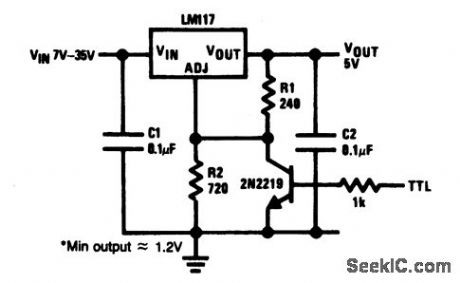
This circuit is suitable for 5-V logic applications and can be shut down electronically with a TTL-level signal. (View)
View full Circuit Diagram | Comments | Reading(701)
PUPILLOGRAPH
Published:2009/7/23 23:11:00 Author:Jessie
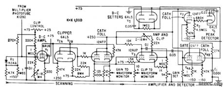
Measures movements of pupil of eye, using flying-spot scanning unit with multiplier phototube, amplifier-detector, and recorder.-G. W. King, Recording Pupil Changes For Clinical Diagnosis, Electronics,32:39, p 67-69. (View)
View full Circuit Diagram | Comments | Reading(768)
300_W_FM_88__to_108_MHz_power_amplifier
Published:2009/7/23 23:11:00 Author:Jessie
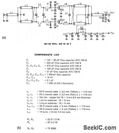


This circuit has a galn of about 9 dB over the frequency range.Thecomponents list,component layout,output power Versus input power and frequency, and gain are shown in Figs. 2-57B, 2-57C, 2-57D, and 2-57E, respectively. The actual layout dimensions are: 4.25 × 2.25 . (View)
View full Circuit Diagram | Comments | Reading(745)
TRIPLE_INPUT_VIDEO_MIXER
Published:2009/7/23 23:11:00 Author:Jessie
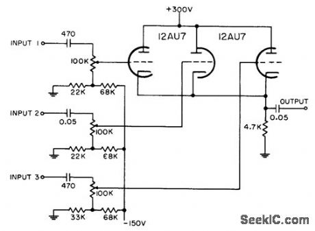
Each grid is biased to cutoff, so mixer accepts only positive-polarity pulses having sufficient amplitude to overcome this bias.-NBS, Handbook Preferred Circuits Navy Aeronautical Electronic Equipment, Vol. 1, Electron Tube Circuits, 1963, p N4-2. (View)
View full Circuit Diagram | Comments | Reading(800)
General_purpose_linear_supply_regulator
Published:2009/7/23 23:11:00 Author:Jessie
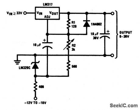
This circuit can be used as a general-purpose lab supply. Although a negative source must be provided, the source does not need to be well regulated. (View)
View full Circuit Diagram | Comments | Reading(560)
100_MC_BANDWIDTH_VIDEO_AMPLIFIER
Published:2009/7/23 23:11:00 Author:Jessie
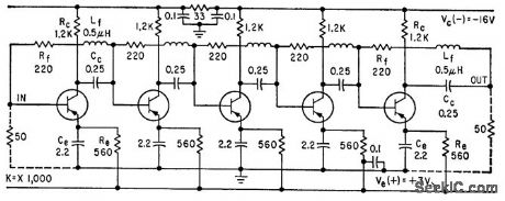
Shunt feedback networks around each stage reduce overall gain at low frequencies, trading gain for bandwidth, so that five cascaded stages give overall gain of 50 db.-J. C. de Broekert and R. M. Scarlett, Transistor Amplifier has 100 Megacycle Bandwidth, Electronics, 33:16, p 73-75. (View)
View full Circuit Diagram | Comments | Reading(545)
Low_impedance_microphone_preamplifier
Published:2009/7/23 23:10:00 Author:Jessie
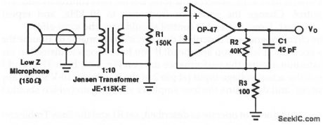
In this preamp, the transformer converts the low microphone impedance up to a value (about 7 kΩ) required by the OP-47 for best noise performance.C1 rolls off the high-frequency response at 90 kHz, giving a noise power bandwidth of 140 kHz. (View)
View full Circuit Diagram | Comments | Reading(1443)
FET_SERVO_AMPLIFIER
Published:2009/7/23 23:55:00 Author:Jessie
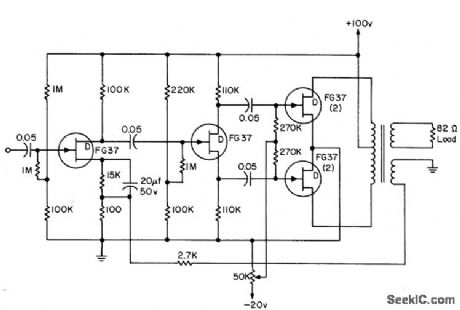
Servo amplifier uses medium-power fet's for 1.5 W output. Circuit has no driver transformer for power stage, and only one electrolytic. Power gain is 70 db, voltage amplification 30 db, input resistance 1 meg, and maximum efficiency 56%.-L. J. Sevin, J., Field-Effect Transistors, McGraw-Hill, N.Y., 1965, p 100. (View)
View full Circuit Diagram | Comments | Reading(2038)
F_V_converter_with_sample_hold_and_active_filter
Published:2009/7/23 23:54:00 Author:Jessie
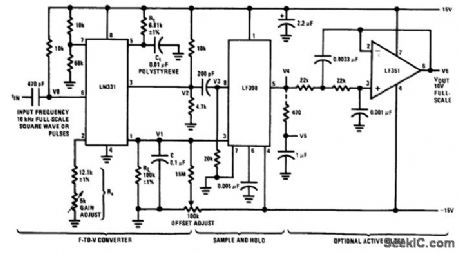
Fig, 12-20 This circuit uses both a sample/hold and an active filter to minimize the ripple/response tradeoff. With the values shown, ripple (at V6) is about 1 mVp-p. Response or settling time to a step change of input frequency is about 60 ms. Linearity is better than 0.1% from 10 kHz down to 500 Hz, but becomes increasingly nonlinear below 500 Hz. To trim, apply 1 kHz and set the offset adjust for 1-V output. Then, apply 10 kHz and set the gain adjust for 10-V Output. National Semiconductor. Linear Applications Handbook 1991,p 1253. (View)
View full Circuit Diagram | Comments | Reading(1050)
Single_chip_audio_amplifier_stereo_2_×0075W
Published:2009/7/23 23:54:00 Author:Jessie

This low-voltage amplifier is for stereo applications (small speaker or headphones ).The circuit operates with battery supplies, from 6V down to 1.6V,and draws low quiescent current (typically 3.2mA with 3-V supply),Closed-loop voltage gain is 26dB with connections as shown, Output is 2×0.075W,with a 4.5-V supply ,operating 32-Ω loads ,The output is reduced to 2×0.035W when the supply is reduced to 3V (with 32-Ωloads). (View)
View full Circuit Diagram | Comments | Reading(644)
STALLED_SERVO_MOTOR_SHUTOFF
Published:2009/7/23 23:54:00 Author:Jessie
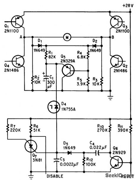
Silicon controlled switch Q7 in timing circuit turns on each time servo motor is actuated, and re moves power from motor if it remains on more than 15 sec, indicating a stall.-D. Perlman, Silicon Switch Turns Off Stalled Servo-motors, Electronics, 39:10, p 90-91. (View)
View full Circuit Diagram | Comments | Reading(598)
8_A_positive_fixed_current_regulcttor
Published:2009/7/23 23:54:00 Author:Jessie
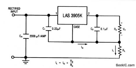
This circuit uses the LAS3905 series voltage regulator (Fig. 7-50) as a fixed-current regulator. Characteristics are shown in Fig. 7-50B, 7-50C, and 7-50D. (View)
View full Circuit Diagram | Comments | Reading(513)
| Pages:1109/2234 At 2011011102110311041105110611071108110911101111111211131114111511161117111811191120Under 20 |
Circuit Categories
power supply circuit
Amplifier Circuit
Basic Circuit
LED and Light Circuit
Sensor Circuit
Signal Processing
Electrical Equipment Circuit
Control Circuit
Remote Control Circuit
A/D-D/A Converter Circuit
Audio Circuit
Measuring and Test Circuit
Communication Circuit
Computer-Related Circuit
555 Circuit
Automotive Circuit
Repairing Circuit