
Circuit Diagram
Index 1118
PREFERRED_TRIODE_DRIVER
Published:2009/7/23 23:35:00 Author:Jessie

Used to amplify video signals for intensity modulation of cathode-ray tube. Accepts positive inputs and gives negative output. Amplification is 5.-NBS, Handbook Preferred Circuits Navy Aeronautical Electronic Equipment, Val. I, Electron Tube Circuits, 1963, PC 27, p 27-2. (View)
View full Circuit Diagram | Comments | Reading(1801)
MULTIMETER_FOR_BLIND
Published:2009/7/3 3:30:00 Author:May
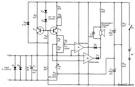
Uses small electric horn to produce sound when DC voltage being measured is different from reference voltage value determined by setting of linear wirewound pot R7. Blind person adjusts R7 for null in sound, then reads Braille dots for that setting to get value of voltage being measured. Use PNP silicon transistors, such as BC177 or BC187.D5 is 4.3.V 400W zener, such as BZX79/CAV3.Other diodes are small-signal silicon, sueh as BA100 or 1N914A.-G. P. Roberts, Multimeters for Blind Students, Wireless World, April 1974, p73-74. (View)
View full Circuit Diagram | Comments | Reading(1115)
2_A_positive_fixed_current_regulator
Published:2009/7/23 23:34:00 Author:Jessie
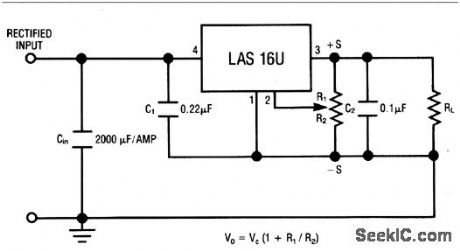
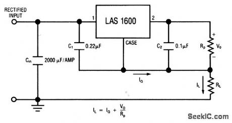
This circuit uses the LAS1600 series voltage regulator (Fig. 7-37A) as a fixed-current regulator. Characteristics are shown in Fig. 7-37B, 7-37C, and 7-37D. (View)
View full Circuit Diagram | Comments | Reading(539)
SERVO_CONTROLLED_GAIN
Published:2009/7/23 23:34:00 Author:Jessie
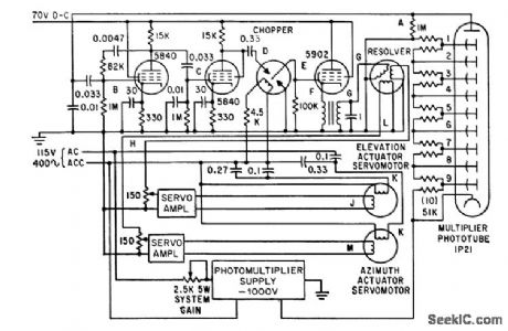
Gain is controlled by varying photomultiplier input volt-ager permitting photoelectric system to track brightness range from remote stars to moon.-W. J. Wichman and M. M. Birnbaum, Servo System Design for Balloon-Borne Star Trackers, Electronics, 34:35, p 43-46. (View)
View full Circuit Diagram | Comments | Reading(700)
HEADLIGHT_DIMMER
Published:2009/7/3 3:29:00 Author:May
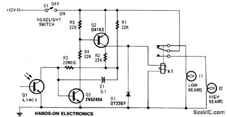
When the lights of an on-coming car are sensed by photo-transistor Q1, things get going. Sensitivity is set by the 22-megohm resistor, R5, to about half a foot-candle. The relay used has a 12-volt, 0.3A coil. The L14C1 is complete with a lens that has a diameter of one inch for a 10° triewing angle. (View)
View full Circuit Diagram | Comments | Reading(1377)
ROAD_ICE_ALARM
Published:2009/7/3 3:27:00 Author:May

The circuit uses a thermistor and three sections of a LM3900 quad op amp IC. When the temperature drops to 36°F the LED indicator flashes about once each second. The flashing rate increases as temperature drops to 32°F when the LED remains on. Amplifier I compares the thermistor's resistance to the resistance of the standard network connected to its noninverting input. Its output-fed to the noninverting input of op amp III-varies with temperature. Op amp II is a free-running multivibrator feeding a pulse signal of about 1 Hz to the inverting input of op amp III. This amplifier compares the outputs of op amps I and II and turns on the LED when the multi-vibrator's output level drops below op amp I. The monitor is calibrated by placing the thermistor in a mixture of crushed ice and water and adjusting the 20 kΩ pot so the LED stays on. (View)
View full Circuit Diagram | Comments | Reading(1069)
MOSFET_RF_STAGE_
Published:2009/7/3 3:26:00 Author:May
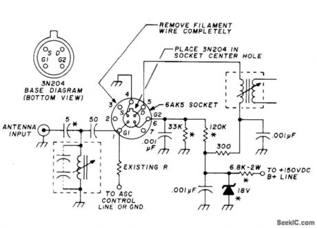
Changing 6AK5 tube to 3N2O4 dual-gate MOSFET improves sensitivity and lowers noise in older VHF FM communication receiver using tubes. Break off center grounding pin of tube socket and cut wires soldered to pin, then connect transistor circuit to tube socket as shown. Replace original resistor going to pin 6 with 120K and run 37K resistor from pin 6 to ground. Move antenna input lead to top of RF input coil, and remove 6-V filament wiring from socket. If tube filaments were in series, replace 6AK5 filament with 36-ohm 2-W resistor. Conversion increases sensitivity to 0.3μγ for 20-dB quieting.-H. Meyer, How to Improve Receiver Performance of Vacuum-Tube VHF-FM Equipment, Ham Fladio, Oct. 1976, p 52-53. (View)
View full Circuit Diagram | Comments | Reading(1767)
PTC_THERMISTOR_AUTOMOTIVE_TEMPERATURE_INDICATOR
Published:2009/7/3 3:25:00 Author:May

The circuit is used to indicate two different water temperature trip points by tuming on LEDs when the temperatures are reached. The circuit is constructed around the LM2904 dual operational amplifter powered from the 12 V auto system. The thermistor is in series with a 10 kΩ resistor from ground to the positive 9.1 V point. The top of the thermistor is tied to both non-inverting inputs of the LM2904. The voltage at these inputs will change as the thermistor resistance changes with temperature. Each inverting input on the LM2904 has a reference, or threshold trip point, set by a 10 kΩ resistor and a 2 kΩ potentiometer in series across the 9.1 V regulated voltage. When this threshold is exceeded on the non-inverting input of LM2904, the TlL220 LED lights. The two trip points can be recalibrated or set to trip at different temperatures by adjusting the 2 kΩ potentiometer in each section. In addition to being used as waming lights as shown here, circuits can be added to turn on the fan motor or activate a relay. (View)
View full Circuit Diagram | Comments | Reading(2541)
AURAL_SWR_INDICATOR
Published:2009/7/3 3:25:00 Author:May

Permits blind amateur radio operator to check standing waves on transmission line and adjust for best possible impedance match between source and load.Darkened areas are foil strips 6 x 70mm, 1.5 mm apart, forming inductive trough that transfers RF energy from transmission line to simple aural monitor. Rectified RF energy changes bias on base of Q1, which makes tone increase in pitch with increasing voltage. ldling tone is about 500 Hz for values shown. Operates from three penlight batteries. Transmitter is peaked for maximum output on rising pitch, and matcbox antenna tuner is adjusted for minimum SWR on descending pitch. To lower audio tone, increase size of 82K resistor.-C. G. Bird, Aural SWR Indicator for the Visually Handicapped, Ham Radio, May 1976, p 53-53. (View)
View full Circuit Diagram | Comments | Reading(855)
AUTOMOTIVE_LIGHTS_ON_WARNING
Published:2009/7/3 3:21:00 Author:May

The SN75604, with input control logic but requiring only one supply rail, can be used in the lights on sensor and alarm driver. The device Vcc and enable inputs are connected to a voltage lead from the light switch. The direction control input is connected to a lead from the ignition switch. Only operation of the lights without the ignition will result in the alarm sounding. The beeper used in this application is an Archer 273-066 that will operate from 3 V to 28 V. At a typical 12 V level, it will produce a pulsating tone of about 95 dB at 30 cm. The alarm on current is about 12 mA when operating from a 12 V supply. (View)
View full Circuit Diagram | Comments | Reading(825)
fast_dc_stabilized_inverting_amplifier
Published:2009/7/23 23:48:00 Author:Jessie
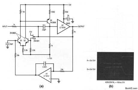
This circuit is similar to that of Fig. 1-21, except that the output is inverted, and the summing-point bias-current is low. Figure 1-22B shows operating waveforms for a 10-V output (trace A input, trace B output). Slew rate is about 100 V/μs, with full power bandwidth of 1 MHz. Output current is about 100 mA. (View)
View full Circuit Diagram | Comments | Reading(704)
TWO_INPUT_MIXER
Published:2009/7/23 23:41:00 Author:Jessie

Used to combine range and heading markers in radar system.-NBS, Handbook Preferred Circuits Navy Aeronautical Electronic Equipment, Vol. 1, Electron Tube Circuits, 1963, p N4-1. (View)
View full Circuit Diagram | Comments | Reading(995)
POWER_SUPPLY_PROTECTION_CIRCUIT
Published:2009/7/3 3:21:00 Author:May

Circuit NotesWhen using a regulated supply to reduce a supply voltage there is always the danger of component failure in the supply and consequent damage to the equipment. A fuse will protect when excess current is drawn, but might be too slow to cope with overvoltage conditions. The values shown are for a 12 V supply being dropped to 5 V. The trip voltage is set to 5.7 V to protect the equipment in the event of a regulator fault. The 330 ohm resistor and the 500 ohm potentiometer form a potential divider which samples the output voltage as set by adjustment of the potentiometer. The SCR is selected to carry at least twice the fuse rating. The full supply voltage is connected to the input of the regulator. The 2N2906 is held bias off by the 10 k resistor and the SCR so that the LED is held off. If the output voltage rises above a set trip value then the SCR will conduct, the fuse will blow, and the 2N3906 will be supplied with base current via the 10 k resistor, and the LED will light up. (View)
View full Circuit Diagram | Comments | Reading(954)
BOOTSTRAPPED_EMITTER_FOLLOWER
Published:2009/7/23 23:41:00 Author:Jessie

Band-width is 1 cps to 5 kc. Gives stable operation in servo systems even with positive feed.back, because loop gain is less than unity.- Transistor Manual, Seventh Edition, General Electric Co., 1964, p 217. (View)
View full Circuit Diagram | Comments | Reading(886)
REVERSING_MOTOR_DRIVE_DC_CONTROL_SIGNAL
Published:2009/7/3 3:20:00 Author:May

This is a positioning servo drive featuring adjustment of balance, gain, and deadband.In addition to control from a dc signal, mechanical input can be fed into the balance control, or that control could be replaced by a pair of resistance transducers for control by light or by temperature. (View)
View full Circuit Diagram | Comments | Reading(695)
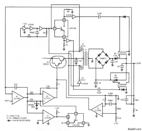
1_X_transfer_function_V_P_converter_10_kHz_to_50_Hz
Published:2009/7/23 23:41:00 Author:Jessie
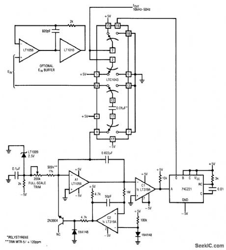
Fig. 12-14 This circuit is more accurate than that or Fig. 12-13, and it converts input voltages of 0 V to 5 V to an output frequency of 10 kHz to 50 Hz with a 0.005% accurate 1/X conformity. Drift is about 50 ppm/℃. One possible disadvantage is that this circuit draws an input current directly proportional to input voltage (to charge the LTC1043 0.01-pF capacitor). When the input voltage is 5 V, the circuit requires about 25 mA at pin 14 of the LTC1043. The optional buffer provides the necessary drive, although the input-voltage range must fall within the common-mode limits of the buffer. To trim, apply 5.000 V and adjust the full-scale trim for 50-Hz output. Linear Technology Linear Applications Handbook 1990, p. AN14-13. (View)
View full Circuit Diagram | Comments | Reading(653)
ISOLATED_PREAMP
Published:2009/7/3 3:20:00 Author:May
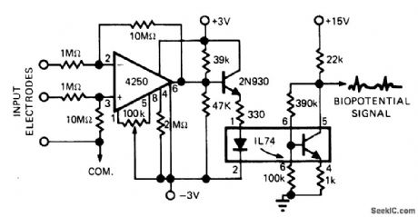
Optoisolator in electrocardiograph preamp circuit prevents circulating ground currents from shocking patients under test. Can be used with practically all other types of AC line-operated equipment in medical en vironments.-R. R. Ady, Let's Take an Illuminating Look at Latest Developments in LED's, EDN Magazine, Aug. 5, 1975, p 30-35. (View)
View full Circuit Diagram | Comments | Reading(713)
SLOW_SWEEP_WIPER_CONTROL
Published:2009/7/3 3:19:00 Author:May

The relay which applies power to the wiper motor is actuated at periodic intervals by the timer circuit, closing the wiper motor contacts.R5 Potentiometer R1 serves as the pulse rate control and potentiometer R5 as the pulse width control. These two controls should be adjusted for optimum performance after the unit is installed in a car. (View)
View full Circuit Diagram | Comments | Reading(1352)
Amplifier_with_±100_V_output_15_V_supply
Published:2009/7/23 23:40:00 Author:Jessie
This amplifier provides a ±100-V output, using ±15-V supplies. The bandwidth is 150 Hz with a slew rate of 0.1 V/μs. Output current is 150 mA. Danger! this circuit involves high voltages!
(View)
View full Circuit Diagram | Comments | Reading(608)
DEMODULATOR
Published:2009/7/3 3:18:00 Author:May

XR-215 PLL IC connected for frequency-seleetive demodulation of FM signals. Value of C0 depends on carrier frequency. C1 detgmines selectivity; for 1-10 MHz, range of C1 is 10-30 times C0. For operation below 5 MHz, RX can be opened; above 5 MHz, use about 75O ohms. - Phase-Locked Loop Data Book, Exar Integrated Systems, Sunnyvale, CA, 1978, p 21-28. (View)
View full Circuit Diagram | Comments | Reading(863)
| Pages:1118/2234 At 2011011102110311041105110611071108110911101111111211131114111511161117111811191120Under 20 |
Circuit Categories
power supply circuit
Amplifier Circuit
Basic Circuit
LED and Light Circuit
Sensor Circuit
Signal Processing
Electrical Equipment Circuit
Control Circuit
Remote Control Circuit
A/D-D/A Converter Circuit
Audio Circuit
Measuring and Test Circuit
Communication Circuit
Computer-Related Circuit
555 Circuit
Automotive Circuit
Repairing Circuit