power supply circuit
Basic_inverting_voltage_regulator
Published:2009/7/23 22:42:00 Author:Jessie | From:SeekIC
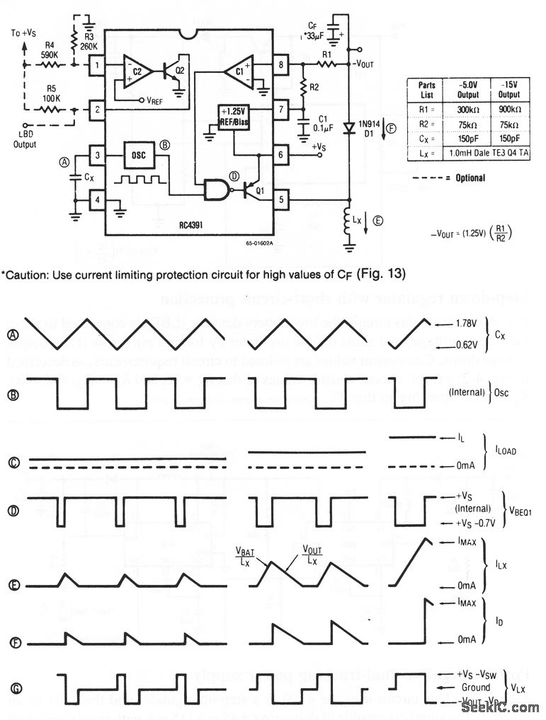
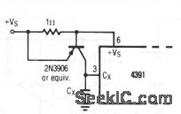
Figures 4-12A and 4-12B show a basic inverting voltage regulator and waveforms, respectively. The outputs are -5 or -15 V, using the values shown.Other outputs can be selected by changing R1 and R2. It may be necessary to change other circuit values. If high values of CF are used, a current-limiting protection circuit (Fig. 4- 12C) might be required.
Reprinted Url Of This Article:
http://www.seekic.com/circuit_diagram/Power_Supply_Circuit/Basic_inverting_voltage_regulator.html
Print this Page | Comments | Reading(3)

Article Categories
power supply circuit
Amplifier Circuit
Basic Circuit
LED and Light Circuit
Sensor Circuit
Signal Processing
Electrical Equipment Circuit
Control Circuit
Remote Control Circuit
A/D-D/A Converter Circuit
Audio Circuit
Measuring and Test Circuit
Communication Circuit
Computer-Related Circuit
555 Circuit
Automotive Circuit
Repairing Circuit
Code: