Electrical Equipment Circuit
Basic_function_test
Published:2009/7/23 23:51:00 Author:Jessie | From:SeekIC


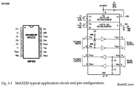
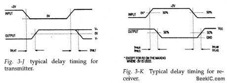
Figure 3-I shows the bypical application circuit and pin configuration for the MAX220.This EIA-232D interface(driver/receiver) operates from 5V,and is also suited for use in systems designed to V.28/V.24 specifications. The basic function is tested by comparing waveforms at the input and output of all four channels. In theory, the waveforms should be identical, except for possible delay. Figures 3-J and 3-K show typical delay timing for both the transmitter and receiver. For reference, the MAX220 receiver delay is 0.6μs (typical) and 3μs (maximum). The trans-mitter delay is 4μs (typical) and 10μs (maximum).
If one or more (but not all) of the four channels shows no output, severe dis-tortion, or excessive delay, the IC is suspect. If all four channels are defective, and +5 V is at pin 16, check the four capadtors (C1 through C4). These capadtors are used in the voltage-doubling (charge pump) and voltage-inverting functions within the IC. If the capacitors are good, and +5-V power is applied, but any or all of the channels are defective, suspqct the IC.
Reprinted Url Of This Article:
http://www.seekic.com/circuit_diagram/Electrical_Equipment_Circuit/Basic_function_test.html
Print this Page | Comments | Reading(3)

Article Categories
power supply circuit
Amplifier Circuit
Basic Circuit
LED and Light Circuit
Sensor Circuit
Signal Processing
Electrical Equipment Circuit
Control Circuit
Remote Control Circuit
A/D-D/A Converter Circuit
Audio Circuit
Measuring and Test Circuit
Communication Circuit
Computer-Related Circuit
555 Circuit
Automotive Circuit
Repairing Circuit
Code: