Electrical Equipment Circuit
VHF_frequency_synthesizer
Published:2009/7/23 22:39:00 Author:Jessie | From:SeekIC


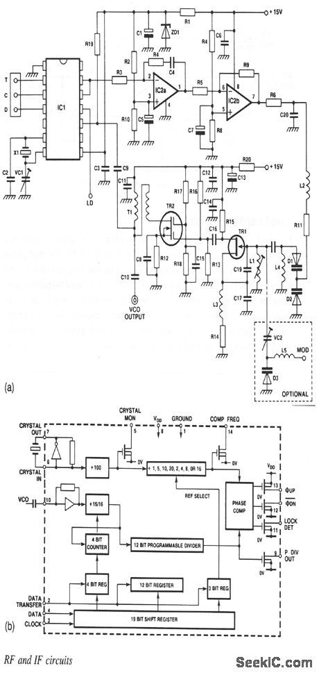
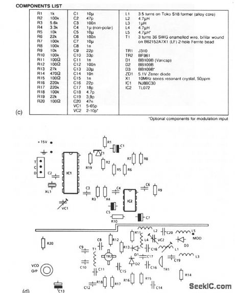
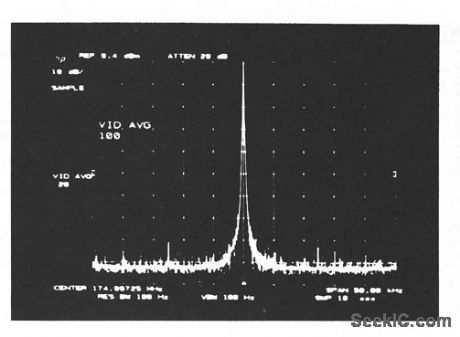
The NF88C30 shown in this circuit contains all the logic required for a high-band VHF PLL synthesizer. Figure 2-41 shows the internal circuits or the chip. The components list is shown in Fig. 2-41 C. As shown in the PC-board layout of Fig. 2-41D, the ground place is split between the VCO and synthesizer-control sections, with dc connections made via narrow tracks on either side of the board.This construction prevents synthesizer currents from causing spurious sidebands in the VCO output. The VCO can be modulated externally by adding L5, D3, and VC2. The output spectrum is shown in Fig. 2-41E. The output power is 9.4 dBm into 50Ω, with a frequency swing of about 10 MHz (from 170 to 1 80 MHz in this case).
Reprinted Url Of This Article:
http://www.seekic.com/circuit_diagram/Electrical_Equipment_Circuit/VHF_frequency_synthesizer.html
Print this Page | Comments | Reading(3)

Article Categories
power supply circuit
Amplifier Circuit
Basic Circuit
LED and Light Circuit
Sensor Circuit
Signal Processing
Electrical Equipment Circuit
Control Circuit
Remote Control Circuit
A/D-D/A Converter Circuit
Audio Circuit
Measuring and Test Circuit
Communication Circuit
Computer-Related Circuit
555 Circuit
Automotive Circuit
Repairing Circuit
Code: