
Circuit Diagram
Index 1082
FLIP_FLOPS_CONTROL_SAMPLE_AND_HOLD
Published:2009/7/23 22:07:00 Author:Jessie

Sampled slices of incoming radar pulse are converted to binary digital form at 10-Mc rate, using flip-flop to connect sample-and- hold capacitor Cs to signal amplifiers. Effective aperture time of sample gate is 20 nsec. Multiplex gate feeds sampled signal values to analog-digital converter at proper time as selected by multiplex counter of system.-A. Hakimoglu and R. D. Kulvin, Sampling Ten Million Words a Second, Electronics, 37:8, p 52-57. (View)
View full Circuit Diagram | Comments | Reading(708)
MICROPROCESSOR_TRIAC_ARRAY_DRIVER
Published:2009/7/5 22:23:00 Author:May
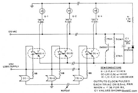
In microprocessor control of multiple loads, the minimum cost per load is critical. A typical application example is a large display involving driving arrays of incandescent lamps. This circuit provides minimal component cost per stage and optocoupler triggering of triac power switches from logic outputs. The minimal component cost is attained by using more complex software in the logic. A darlington output optocoupler provides gate current pulses to the triac, with cost advantages gained from eliminating the current limiting resistor and from the low cost coupler. The trigger current source is a dipped tantalum capacitor, charged from the line via a series resistor with coarse voltage regulation being provided by the darlington signal transistor. The resistor and capacitor are shared by all the darlington-triac pairs and are small in size and cost due to the low duty cycle of pulsing. Coupler IRED current pulses are supplied for the duration of one logic clock pulse (2-10μsec), at 0.4 to 1 msec intervals, front a LED driver LC. The pulse timing is derived from the clock waveform when the logic system requires triac conduction.
A current limiting resistor is not used, which prevents Miller effect slowdown of the H11G2 switching speed to the extent the triac is supplied insufficient current to trigger.Optodarlington power dissipation is controlled by the low duty cycle and the capacitor supply characteristics. (View)
View full Circuit Diagram | Comments | Reading(1566)
A_C_TO_D_C_CURRENT_STANDARDIZATION
Published:2009/7/23 22:04:00 Author:Jessie
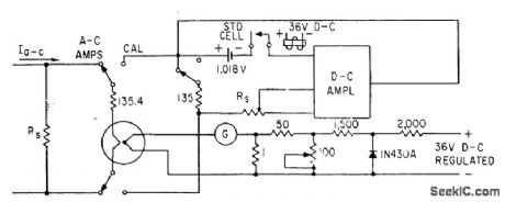
Used to standardize alternating currents directly to standard cell-E. A. Gilbert, Feed-back Circuits for A-C Instrument Calibration, Electronics, 33:40, p 94-96. (View)
View full Circuit Diagram | Comments | Reading(508)
VARIABLE_AUDIO_OSCILLATOR,20_Hz_TO_20_kHz
Published:2009/7/5 22:23:00 Author:May

To obtain a 1000:1 Sweep Range, the vol-tage across external resistors RA and RB must decrease to nearly zero. This requires that the highest voltage on control pin 8 exceed the voltage at the top of RA and RB by a few hundred millivolts. The circuit achieves this by using a diode to lower the effective supply voltage on the 8038. The large resistor on pin 5 helps reduce duty cycle variations with sweep. (View)
View full Circuit Diagram | Comments | Reading(838)
50_30000_Hz_WlEN_BRIDGE
Published:2009/7/5 22:23:00 Author:May
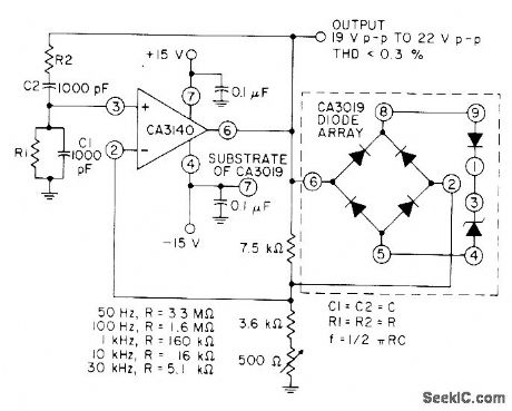
Wide-range audio oscillator utilizes high input impedance, high slew rate, and high voltage characteristics of CA3140 opamp in combination with CA3019 diode away. RI and R2 are same value, chosen for frequency desired as given in table.- Circuit Ideas for RCA Linear ICs, RCA Solid State Division, Somerville, NJ, 1977, p 4. (View)
View full Circuit Diagram | Comments | Reading(1295)
CLOSED_RING_COUNTER
Published:2009/7/23 22:04:00 Author:Jessie

Serves as 20-channel electronic switch for sampling voltage sources at rates of up to 50,000 cps. Flip-flop ring actuates diode gates in step with trigger pulses. Output can be used to drive recorders or feed data processing equipment.-K. L. Bents and B. E. Bishop, High-Speed Multiplexing With Closed-Ring Counters, Electronics, 32-26, p 48-50. (View)
View full Circuit Diagram | Comments | Reading(809)
50_kHz_OSCILLATOR
Published:2009/7/5 22:21:00 Author:May


A 50 kHz circuit is possible becasuse of the more nearly ideal characteristics of the D5K. (View)
View full Circuit Diagram | Comments | Reading(922)
Wireless remote control transmitting and receiving circuit composed of the RX5019/5020
Published:2011/8/1 1:56:00 Author:Christina | Keyword: Wireless, remote control, transmitting, receiving
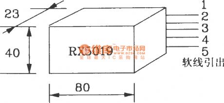

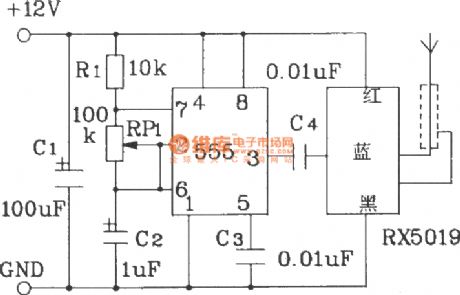
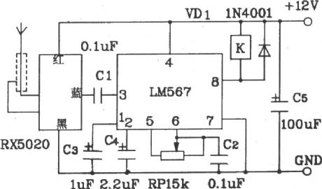
The RX5019/5020 is designed as one kind of wireless remote control transmitting and receiving circuit. The operating frequency of it is stable and not easy to change, the circuit is simple and east to use, you can use it by connecting the outgoing line with the power and signal. They can be used alone or together, it is the perfect wireless remote control launch/receiving device.
The transmitting distance of it can be 3-5km in the unobstructed environment, and the transmitting distance can be 1-3km in the city. If the occasion is fixed, you can use a coaxial cable to connect it with the rod antenna, so the air signal transmission distance can be 8km. The the signal input of the emission component RX5019 can be the voice signals or the audio oscillator signals, the music IC signals and the microphone signals.
(View)
View full Circuit Diagram | Comments | Reading(1918)
IONIZATION_ALARM_USING_TRANSISTORS
Published:2009/7/5 22:21:00 Author:May

Use of continuous smoke alarm signal rather than beeping horn simplifies transistor circuits needed to trigger fire alarm and low-battery alarm. When high impedance of ionization chamber is lowered by smoke or gas, amplifier Q1-Q2-Q3 supplies 100-μA base current to Darlington Q4 for powering hom continuously as Iong as smoke content exceeds that set by threshold control R5. Low-battery circuit is tdpped at voltage range between 9.8 and 11.2 V, as determined by R13, to energize MVBR Q8-Q9 for driving horn 0.7 s, with 50-s OFF intervals.Battery is chosen to last at least t year while furnishing standby current of about 70μA.-A.Pshaenich, Solid State Gas/Smoke Detector Systems, Motorola, Phoenix, AZ, 1975, AN-735,p 8. (View)
View full Circuit Diagram | Comments | Reading(1256)
STABLE_OPTOCOUPLER
Published:2009/7/5 22:21:00 Author:May

A circuit stabilizes the current-transfer ratio (CTR) of an optically coupled isolator used as a linear transducer. The optocoupler produces a voltage output that is proportional to-but electrically isolated from-the voltage input. However, the output voltage is directly affected by changes in the CTR, and the CTR can change substantially with temperature and current. To a lesser extent the CTR changes with time over the life of the optocoupler. The circuit employs a feedback circuit containing a second optocoupler.
The feedback signal tends to oppose changes in the overall CTR. (View)
View full Circuit Diagram | Comments | Reading(2907)
AM_SSB_CW_IF_strip
Published:2009/7/23 22:03:00 Author:Jessie

This circuit shows an SL6700C(Fig.2-13)connected to form an AM/SSB/CW IF strip.The SL621 is an AGC generator that is designed specifically for SSB operation. (View)
View full Circuit Diagram | Comments | Reading(1552)
10_kHz_OSCILLATOR
Published:2009/7/5 22:20:00 Author:May

The capacitor charges until switching vol-tage is reached. When SUS switches on, the inductor causes current to ring. When the cur-rent thru SUS drops below the holding current, the device turns off and the cycle repeats. (View)
View full Circuit Diagram | Comments | Reading(706)
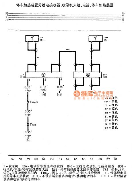
Audi A6 Parking Hating Circuit
Published:2011/7/28 17:54:00 Author:Robert | Keyword: Audi, Parking, Hating
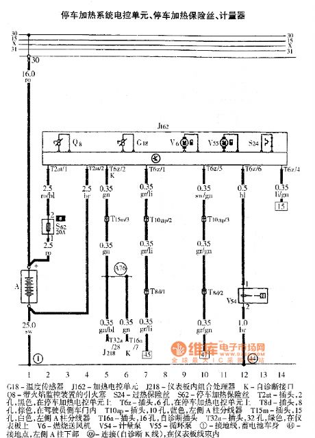
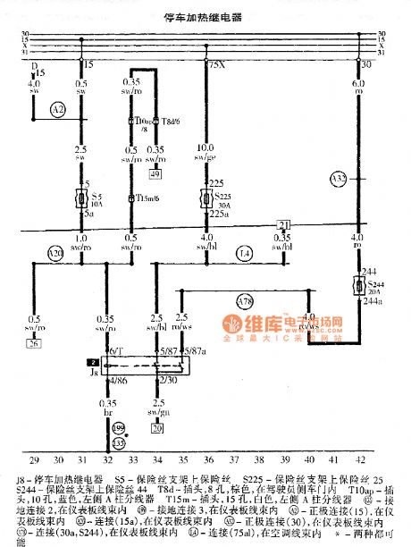

The pictures show the Audi A6 parking heating device circuits.
The first picture shows the parking heating system ECU, parking heating fuse and the meter device.
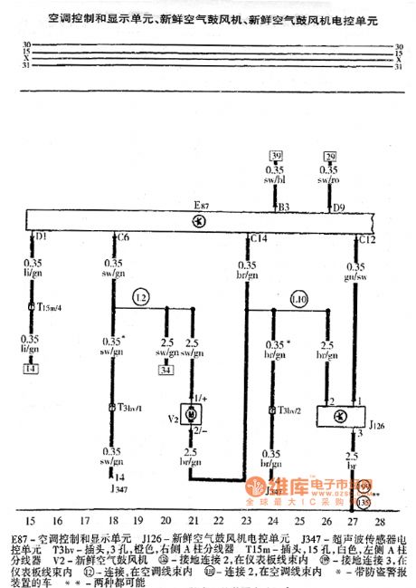
The second picture shows the air conditioner control and display unit, fresh air blower ECU.
The third picture shows the parking heating relay.
The fourth picture shows the timer, heating indication lamp.
The fifth picture shows the parking heating device wireless receiver, tape recorders antenna, telephone, parking heating device. (View)
View full Circuit Diagram | Comments | Reading(860)
CXAl261M (TV) infrared remote control receiving preamplifier circuit
Published:2011/8/1 8:20:00 Author:Christina | Keyword: TV, infrared, remote control, receiving, preamplifier circuit
The CXAl261M is designed as the silicon monolithic integrated circuit. It has the same technical characteristics, absolute maximum ratings, main electrical specifications, logic diagram and typical application circuits with the CX20106A excepts the shape structure.
(View)
View full Circuit Diagram | Comments | Reading(467)
Audi A6 Central Door Lock, Anti-Theft Alarm System And Internal Monitoring Control System Circuit
Published:2011/7/28 18:16:00 Author:Robert | Keyword: Audi, Central Door, Lock, Anti-Theft, Alarm, Internal, Monitoring, Control


The pictures show the Audi A6 central door lock, anti-theft alarm system and internal monitoring control system circuits.
The first picture shows the ECU, engine hood anti-theft alarm contacting switch, central door lock and anti-theft device antenna, anti-theft alarm device.
The second picture shows the central door lock ECU, driver side-door lock switch.
The third picture shows the central door lock ECU, driver side-door contacting switch.
The fourth picture shows the central door lock ECU, front passenger side-door contacting lock, front passenger side-door internal lock switch.
The fifth picture shows the central door lock ECU, left door alarm lamp, right door alarm lamp.
The sixth picture shows the central door lock ECU, left-rear door contacting switch, right-rear door contacting switch. (View)
View full Circuit Diagram | Comments | Reading(2140)
350_Hz_STABILIZED_SINE_WAVE
Published:2009/7/5 22:20:00 Author:May

Squarewave oscillator Q2-Q3 stabilized by Q1, followed by passive filter and active filter using μA709, produces amplitude-stabilized sine wave at 350 Hz, for which third harmonic is 39 dB down and other harmonics are insignificant.-E. Neugroschel and A. Paterson, Amplitude-Stabilized Audio Oscillator, EEE Magazine, April 1971, p 65. (View)
View full Circuit Diagram | Comments | Reading(577)
Time-Varying Dimming Circuit
Published:2011/7/29 8:47:00 Author:Robert | Keyword: Time, Varying, Dimming
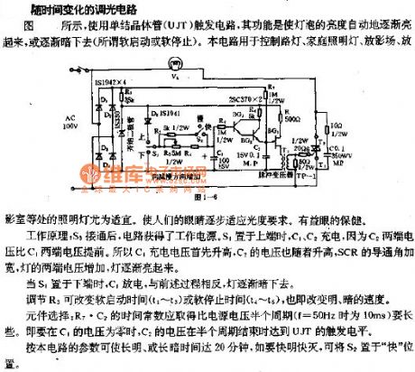
The picture shows the time-varying dimming circuit.As shown, it uses the unijunction transistor (UJT) trigger circuit, whose function is that it could make the lamp's brightness light up gradually and automatically, or light out gradually and automatically (which means the so-called soft starting or soft stopping). This circuit could be used to control street lamp, home lamp, film-playing place, film-playing room and so on, and these cases would be very adequate. This could make people's eyes adapt to the photometric requirements gradually, so that it is good for eye's health.The working principle: when the S3 is connected, the circuit would get power supply. If the S1 is switched to upside, the C1, C2 would be charged. Because the C2's two ports' voltage is advanced than the C1's two ports' voltage, the C1's charging voltage would be increased firstly and the C2 voltage would follow it to be increased. The SCR's conduction angle would be wider and the lamp's two ports' voltage would be increased, so the lamp would be light up gradually. (View)
View full Circuit Diagram | Comments | Reading(608)
BX-1387/BX-1407 (TV, video tape recorder, audio equipment and air conditioner) infrared remote control receiving circuit
Published:2011/8/1 8:26:00 Author:Christina | Keyword: TV, video tape recorder, audio equipment, air conditioner, infrared, remote control, receiving circuit
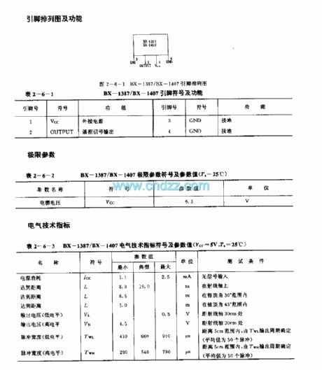
The BX-1387/BX-1407 is designed as the infrared remote control receiving circuit that can be used in the TV, video tape recorder, audio equipment and air conditioner applications. The carrier frequency of the BX-1387 is 40kHz, the carrier frequency of the BX-1407 is 38kHz.
Features
It uses the lastest hybrid circuit technology, so there is no need of the external components.It uses the square pot-type package, the internal circuit has the needle-like optical diode and the preamplifier integrated circuit CX20106A.The high reliability, small size, low voltage and low power consumption.The power voltage range is 4.7-5.3V.It is in the 4-pin square pot-type package.
(View)
View full Circuit Diagram | Comments | Reading(2940)
INTEGRATED_SOLID_STATE_RELAY
Published:2009/7/5 22:19:00 Author:May

A complete zero-voltage switch solid-state relay contains an input circuit, an output circuit, and the power thyristor. The circuit illustrates a triac power thyristor with snubber circuit and GE-MOVR II Varistor transient over-voltage protection. The 22 ohm resistor shunts di/dt currents, passing through the bridge diode capacitances, from the triac gate, while the 100 ohm resistor limits surge and gate currents to safe levels. Although the circuits illustrated are for 120-V rms operation, relays that operate on 220 V require higher voltage ratings on the MOV, rectifier diodes, triac, and pilot SCR. The voltage divider that senses zero crossing must also be selected to minimize power dissipation in the transistor optisolator circuit for 220-V operation. (View)
View full Circuit Diagram | Comments | Reading(2677)
UART_INTERFACE
Published:2009/7/5 22:19:00 Author:May

Uses TMS-6011 UART to convert parallel data into serial data and back again for Altair 8800 microprocessor. UART mates directlyto computer bus, because all outputs from UART are three-state buffers with separate enable lines provided for status bits and 8 bits of parallel output. Pin 22 is high when UART can accept another character for conversion. Pin 18 must be pulsed low to reset pin 19 so it can signal receipt of another character.Connections to pins 35-39 depend on I/0 devices used, as covered in article.-W. T. Walters, Build a Universal I/O Board, Kilobaud, Oct. 1977, p 102-108. (View)
View full Circuit Diagram | Comments | Reading(2406)
| Pages:1082/2234 At 2010811082108310841085108610871088108910901091109210931094109510961097109810991100Under 20 |
Circuit Categories
power supply circuit
Amplifier Circuit
Basic Circuit
LED and Light Circuit
Sensor Circuit
Signal Processing
Electrical Equipment Circuit
Control Circuit
Remote Control Circuit
A/D-D/A Converter Circuit
Audio Circuit
Measuring and Test Circuit
Communication Circuit
Computer-Related Circuit
555 Circuit
Automotive Circuit
Repairing Circuit