
Circuit Diagram
Index 1084
11_16_MHz_IN_10_Hz_STEPS
Published:2009/7/5 22:04:00 Author:May
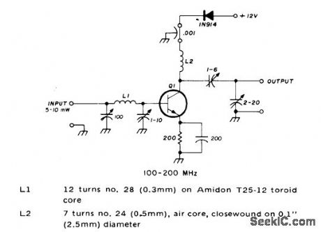
1.1-1.6 MHz IN 10-Hz STEPS-Data input re|quirement is parallel BCD with 10-V CM0S levels and five digits. Reference input is 1-MHz sine or square with at least 1 VP-P. VC0 covers 110-160 MHz in 1-kHz steps, operating in loop haying 1-kHz reference. VCO signal is divided by 100 to give final output in 10-Hz steps. L1 is 6 turns No. 22 on 3-mm form, tapped at 2 turns.RFC is 6 turns No. 28 on F754-1-06 ferrite bead.T1 is Mini-Circuits Lab T16-1 broadband RF transformer.-R. C. Petit, Frequency Synthesized Local-Oscillator System for the High-Frequency Amateur Bands, Ham Radio, Oct. 1978,p 60-65. (View)
View full Circuit Diagram | Comments | Reading(671)
AUDIO_POWERED_NOISE_CUPPER
Published:2009/7/5 22:04:00 Author:May

T1 and T2 are 600 to 8 ohm transformers (any transistor radio output transformers with 500 to 4 ohm impedance may be used). Q1 is a 2N2222 npn transistor, and Q2 is a 2N2907 pnp transistor. D1 and D2 1N270 signal diodes (HEP 134 or 135). Two transistors, powered by the audio power contained within the signal, will clip signal peaks which exceed the threshold established by the 2.5 K potentiometer. The diodes isolate the positive and negative clipping circuits represented by the npn and pnp transistors, respectively. A desired audio operating level can be established and the potentiometer needs little or no further adjustment. (View)
View full Circuit Diagram | Comments | Reading(1281)
Infrared Remote-Control Receiver Head Substitution Method Circuit
Published:2011/7/29 18:23:00 Author:Robert | Keyword: Infrared, Remote-Control, Receiver Head, Substitution, Method
The picture shows the infrared remote-control receiver head substitution method circuit.
The infrared receiver head, which is used in the household appliances with remote-control function, has a big range of models. So when repairing it usually meets the case of unable buying the original model of receiver head. And it could only to find a substitution product. In practice it could use the common models for substitution of whatever types of the receiver heads. When it needs substitution it should be noted that:1.Mounting dimensions.If the original model of receiver head has a large size then it would select expediently any size-equivalent models for substitution and also it can use a smaller size model for substitution. Currently there is a micro-receiver head which looks like a plastic-package triode. It could be used for repairing substitution conveniently. (View)
View full Circuit Diagram | Comments | Reading(649)
Homemade wireless video doorbell circuit
Published:2011/7/26 2:14:00 Author:Christina | Keyword: Homemade, wireless, video doorbell
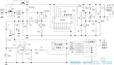
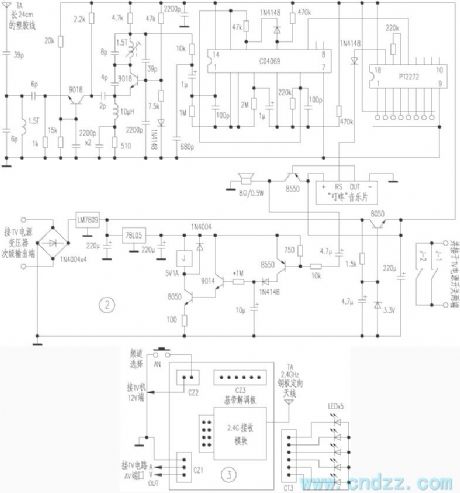
Figure 1 is the outdoor circuit, AN1 and AN2 are the buttons of the doorbell, when the guest presses the button of the doorbell, one channel of the power supply supplies the power to the coding launch circuit through the AN2, the coding launch circuit outputs the 315MHz coded signal, at the same time the power supply charges the 10μF timing capacitor through 1N4148. Another channel of the power supply supplies the power to the delay circuit through the AN1, the relay gets power to close, the contact point J-1 closes to protect itself. And the LM386 forms the voice pick-up circuit, the video camera and the 2.4GHz transmitter module all get power to work, the transmitter module outputs the high frequency signal which is modulated by the AV signal.
(View)
View full Circuit Diagram | Comments | Reading(2461)
Homemade wireless remote control intermediate frequency switcher circuit
Published:2011/7/26 2:05:00 Author:Christina | Keyword: Homemade, wireless, remote control, intermediate frequency, switcher circuit
Operating principle: the principle diagram of the wireless medium frequency switcher is as shown in figure 1. A1 is the wireless remote control dedicated transmitter module, when you press the switch S to connect the power, the built-in transmitting antenna sends the 280MHz ~ 300MHz ultra-high frequency modulation electromagnetic wave to the surrounding space, it is received by the built-in receiving antenna of the dedicated receiver module A2 in the effective distance, then it is modulated, amplified, detected, transformed by the A2 module, the output port outputs the high level pulse to conduct VT5 and control the operating of IC.
(View)
View full Circuit Diagram | Comments | Reading(1916)
NOISE_LIMTER
Published:2009/7/5 22:02:00 Author:May

This limiter improves signal-to-noise ratio. It is connected between the detector output and the audio input (if high impedance) or at some relatively high-impedance section between two audio stages-preferably the low level stages. D1 and D2 can be any diode having relatively low forward resistance and very high back resistance. The circuit is excelent for receivers having bandwidths down to 2 or 3 kHz. Increase the value of C1 for receivers having narrower bandwidths. (View)
View full Circuit Diagram | Comments | Reading(876)
BALANCE_AMPLIFIER_WITH_LOUDNESS_CONTROL
Published:2009/7/5 22:01:00 Author:May

View full Circuit Diagram | Comments | Reading(831)
PRECISE_AUDIO_CLIPPER
Published:2009/7/5 22:00:00 Author:May

A differential amplifter makes an excellent audio clipper and can provide precise, symmetrical clipping. The circuit shown commences clipping at an input of 100 mV. The output commences clipping at ±3V. Matching Q7 and Q2 is necessary for good symmetrical clipping. (If some asymmetry can be tolerated, this need not be done.) (View)
View full Circuit Diagram | Comments | Reading(2431)
AUDIO_SQUELCH_CIRCUIT
Published:2009/7/5 22:00:00 Author:May

This simple audio squelch unit suppresses all input signals below a preset threshold. (View)
View full Circuit Diagram | Comments | Reading(3503)
Intelligent wireless security system design circuit
Published:2011/7/26 1:52:00 Author:Christina | Keyword: Intelligent, wireless, security system, design circuit

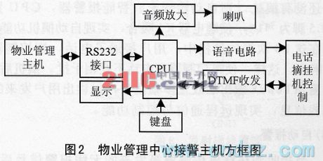
The intelligent wireless security system is composed of the sensor, the family intelligent alarm, the property management center alarm-receiving host computer and the related control management softwares. Figure 1 is the block diagram of the family intelligent alarm, figure is the block diagram of the property management center alarm-receiving host computer.
1.1 The host computer circuit
As the figure 1 shows, the RF receiving module of the host computer circuit receives the alarm signal of the sensor, and alarm signal is decoded by the decoder (PT2272), so we get the address and data type of the alarm sensor, only when the host computer address and the sensor address are the same, the signal can be received by the host computer.
(View)
View full Circuit Diagram | Comments | Reading(2398)
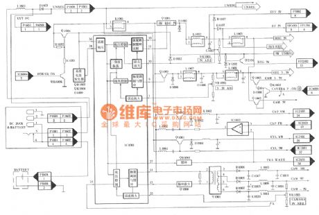
NV-M8000 Camera Box-Out Control Working Principle Circuit And Common Troubleshooting Circuit
Published:2011/7/29 19:03:00 Author:Robert | Keyword: Camera, Box-Out, Control, Working Principle, Common, Troubleshooting
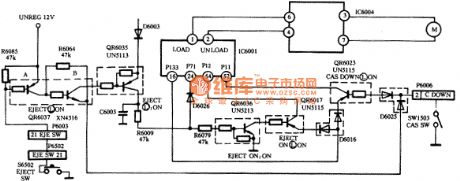
The NV-M8000 camera box-out control circuit is made up of system control microprocessor IC6001 and transistors QR6037, QR6035, QR6036, QR6017, QR6023 and EJECT button switch S6520 and cassette holder down switch SW1503 and so on, which is shown in the picture.
The working principle.
When it is in cassette holder down mode, the cassette holder down switch SW1503 would be connected under the function of the cassette holder lockplate control lever. The QR6023's base polar would connect the plug-in module D6006's pin 2 through K6025, and then through the cassette holder down switch it gets to the ground. QR6023's base polar is conducted in low voltage level. IC6001's pin 16 (CSANOUT) signal would connect the its pin 52 (CSANIN) through QR6023. The microprocessor would be in stopping mode when it receives the cassette holder down signal. (View)
View full Circuit Diagram | Comments | Reading(735)
Intelligent infrared remote control circuit design
Published:2011/7/26 1:36:00 Author:Christina | Keyword: Intelligent, infrared, remote control, design


The structure of the intelligent infrared remote controller is as shown in figure 1, this device is composed of the single-chip microcomputer, the infrared receiving part, the display circuit, the memory, the button and undervoltage indication circuit. This circuit can be driven by two batteries. The single-chip microcomputer uses the infrared remote control transmitter chip BA5048, the operating power voltage is 1.5-5V. The memory, LCD and the infrared emitter all have the ready-made 3V voltage products, the common infrared receiver IC (such as the CX20106, HS0038) has the rated operating voltage of 5V, it is hard to find the low voltage infrared receiver.
(View)
View full Circuit Diagram | Comments | Reading(1392)
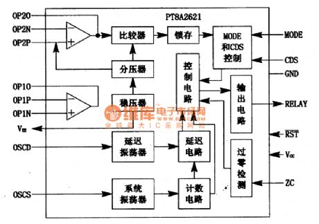
PT8A2621 Infrared Induction Lamp Controlled Intergrated Circuit
Published:2011/7/23 2:51:00 Author:Michel | Keyword: Infrared Induction, Lamp Controlled, Intergrated Circuit
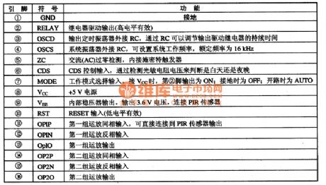
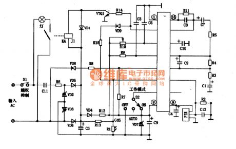
PT8A2621 is large-scale integrated circuit with CMOS technology produced by PT company.It is mainly used in the infrared inductive movement of human body lamp control.The PT8A2621 uses relay control method, which can be widely used in the corridor, kitchen,courtyard, conference room, warehouse, the energy saving of lighting handicraft etc.
First,Pins Functions and Inside Circuit Block Circuit
PT8A2621 has 16 feet DP or SDP package and its pins functions are shown as table.Its inside circuit block diagram of intergrated circuit is shown as picture 1.
Table 1: PT8A2621 Pins Functions
Second,Typical Application Circuit
Typical application circuit of PT8A2621 is shown as picture 2.The S1 switch in the figure is used as excessive control.The voltage is provided by rectifier voltage regulating circuit and relay KAJ1 is used to control the lamp.
(View)
View full Circuit Diagram | Comments | Reading(850)
HANDSHAKING
Published:2009/7/5 21:59:00 Author:May
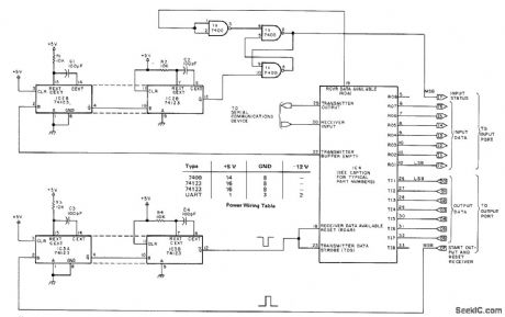
Circuit sets up operating connection between computer and UART (universal asynchronous receiver-transmitter). Eighth bits of I/O ports indicate when data has been successfully transmitted and system is ready to transmit more information. Can be adapted to ny 8-bit computer. IC4 is standard UART such as Signetics 2536, General lnstruments AY 5 1012, Texas Instruments TMS 6011, or American Microsystems S1883. Receiver of UART has seven data lines connected to input port. Article covers handshaking operation in detail and gives typical software routines for parallel I/O handshaking. Technique permits running UART at any desired clock speed, as long as all clocks in system are matched.-T. McGahee, Save Software: Use a UART for Serial IO, BYTE, Dec.1977, p 164-166. (View)
View full Circuit Diagram | Comments | Reading(2530)
Panasonic M3500 Camera Power Supply Working Principle Circuit And Troubleshooting Circuit
Published:2011/7/29 19:29:00 Author:Robert | Keyword: Panasonic, Camera, Power Supply, Working Principle, Troubleshooting
The Panasonic M-series Cameras are popular in the counties and television enterprises, schools, audio-visual halls, individual wedding camera crews and some families, and the society has a large amount of these products. This series has many advantages such as full functions, easy to use, good video quality, video tapes can be played directed by the VHS camera and so on. Currently these cameras have entered the maintenance period. So the author take the Panasonic NV-M3500 type camera as example to introduce this type of devices' circuit principle and troubleshooting method. In the circuit, those types which is similar to this types such as NV-M3000, NV-M9000, NV-M9500, NV-DP200 and other types and the Panasonic M series old types such as NV-M7, NV-M1000, NV-M8000 and other cameras, could also take reference from the method introduced in this article for maintenance. (View)
View full Circuit Diagram | Comments | Reading(2050)
001_ANALOG_MULTIPLIER
Published:2009/7/5 21:58:00 Author:May
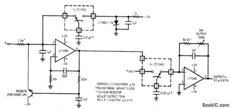
The F→V input frequency is locked to the U→F output because the LTC1043's clock is common to both sections. The F→V's reference is used as one input of the multiplier, while the U→F furnishes the other. To calibrate, short the X and Y inputs to 1.7320 V and trim for a 3-V output (View)
View full Circuit Diagram | Comments | Reading(714)
STK3048+SAP15N/P Power Amplifier Circuit Restructured From The Original Board
Published:2011/8/2 5:02:00 Author:Robert | Keyword: Power Amplifier, Restructure, Original, Board

The features of this power amplifier are listed here:1.It needn't to make printed board by yourself and it would be easy to restructure. 2.It has no large loop circuit negative feedback and this would improve the transient response. 3.The middle point outputs DC servo to make the middle point's voltage be zero all the way. 4.Its static current could be adjusted anyway which depends on the user's favor. 5.Its front and back stages can be suit for one group of power supply and it needs not to add other transistors. The circuit is simple.
The new audio large-power tube SAP15N/P's package is single in-line 5-pin package. It has built-in temperature compensation diode, push tube, end large-power tube and emitter polar large-power resistor. (View)
View full Circuit Diagram | Comments | Reading(2706)
8OO_Hz_SINGLE_TRANSlSTOR
Published:2009/7/5 21:58:00 Author:May

Ladder network determines frequency. For higher frequencies, decrease values of capaeitors in network.Circuit also works with OC-2. SK-3004. and AT30H transistors.-Circuits. 73 Magazine. May 1977. p 31. (View)
View full Circuit Diagram | Comments | Reading(1038)
ANALOG_MULTIPLIER
Published:2009/7/5 21:57:00 Author:May

View full Circuit Diagram | Comments | Reading(2266)
CLOSED_LOOP,TACHOMETER_FEEDBAGK_CONTROL
Published:2009/7/5 21:54:00 Author:May

The system utilizes the H21A1 and a chopper disc to provide superior speed regulation when the dynamic characteristics of the motor system and the feedback system are matched to provide stability. The tachometer feedback system illustrated was designed around specific motor/load combinations and may require modification to prevent hunting or oscillation with other combinations. This dc motor control utilizes the optachometer circuit previously shown to control a P.U.T. pulse generator that drives the D44E1 darlington transistor which powers the motor. (View)
View full Circuit Diagram | Comments | Reading(1849)
| Pages:1084/2234 At 2010811082108310841085108610871088108910901091109210931094109510961097109810991100Under 20 |
Circuit Categories
power supply circuit
Amplifier Circuit
Basic Circuit
LED and Light Circuit
Sensor Circuit
Signal Processing
Electrical Equipment Circuit
Control Circuit
Remote Control Circuit
A/D-D/A Converter Circuit
Audio Circuit
Measuring and Test Circuit
Communication Circuit
Computer-Related Circuit
555 Circuit
Automotive Circuit
Repairing Circuit