Remote Control Circuit
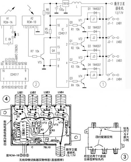
Homemade wireless remote control intermediate frequency switcher circuit
Published:2011/7/26 2:05:00 Author:Christina | Keyword: Homemade, wireless, remote control, intermediate frequency, switcher circuit | From:SeekIC

Operating principle: the principle diagram of the wireless medium frequency switcher is as shown in figure 1. A1 is the wireless remote control dedicated transmitter module, when you press the switch S to connect the power, the built-in transmitting antenna sends the 280MHz ~ 300MHz ultra-high frequency modulation electromagnetic wave to the surrounding space, it is received by the built-in receiving antenna of the dedicated receiver module A2 in the effective distance, then it is modulated, amplified, detected, transformed by the A2 module, the output port outputs the high level pulse to conduct VT5 and control the operating of IC.
Reprinted Url Of This Article:
http://www.seekic.com/circuit_diagram/Remote_Control_Circuit/Homemade_wireless_remote_control_intermediate_frequency_switcher_circuit.html
Print this Page | Comments | Reading(3)

Article Categories
power supply circuit
Amplifier Circuit
Basic Circuit
LED and Light Circuit
Sensor Circuit
Signal Processing
Electrical Equipment Circuit
Control Circuit
Remote Control Circuit
A/D-D/A Converter Circuit
Audio Circuit
Measuring and Test Circuit
Communication Circuit
Computer-Related Circuit
555 Circuit
Automotive Circuit
Repairing Circuit
Code: