
Circuit Diagram
Index 1089
CMOS_RE_video_multiplexer
Published:2009/7/23 22:13:00 Author:Jessie
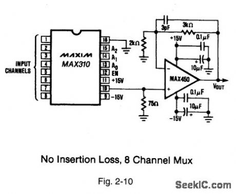
Figure 2-10 shows a typical application circuit and pin configurations for the MAX310/11. The key feature of the IC is extremely high off-isolation at high frequencies. The isolation of each off channel to the output is guaranteed to be -66 dB at 5 MHz. The input signal range is +12 V to -15 V with t15-V supplies.Power consumption is typically 1.1mW. All control inputs are fully compatible with TTL and CMOS. Decoding is in standard BCD. An enable input is provided to simplify cascading of the ICs. The ICs will operate with power supply combinations that total less than 36 V (V+ - V-), including single-supply operation at +12 V, +15-V, and +28 V with V- connected to ground. MAXIM HIGH-RELIABILITY DATA Book, 1993, P. 1-1. (View)
View full Circuit Diagram | Comments | Reading(616)
BASIC_HYBRID_UJT_PNP_TIMER
Published:2009/7/23 22:13:00 Author:Jessie
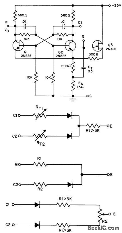
Serves as symmetrical square-wave mvbr when fixed or variable resistor is connected between E and G. Serves as one-hot mvbr when fixed or variable resistor is connected between C1 and E. Other configurations shown for external connections give constant or variable-frequency nonsymmetrical multivibrators.- Transistor Manual, Seventh Edition, General Electric Co., 1964, p 338. (View)
View full Circuit Diagram | Comments | Reading(605)
HT-7605 (alarm, lighting and industrial control) pyroelectric infrared receiver control circuit
Published:2011/8/1 4:21:00 Author:Christina | Keyword: alarm, lighting, industrial control, pyroelectric, infrared, receiver control


The HT-7605 is designed as the pyroelectric infrared receiver control circuit that can be used in the alarm, lighting and industrial control applications. The internal circuit is composed of the system oscillator, the delay oscillator, the voltage regulator, the operational amplifier, the voltage stabilizer, the latch circuit, the delay circuit, the zero crossing trigger circuit, the control circuit, the beep excitation circuit, the LED excitation circuit, the relay excitation circuit, the SCR excitation circuit and the testing circuit.
Features
Single chip type.Micro-power consumption.High integration, little external components, high sensitivity.Stable performance.
(View)
View full Circuit Diagram | Comments | Reading(463)
HYDROPHONE_PREAMP
Published:2009/7/23 22:13:00 Author:Jessie
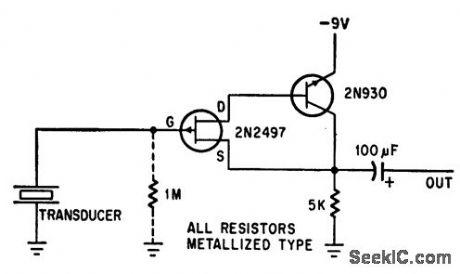
Fet eliminates unwanted noise and added capacitance caused by long cobias connecting hydrophone to shore station, Voltage gain is unity. Can be used with cables UP to 3.000 feel long. if hydrophone moves in water, use 1-meg resistor between gate and ground to suppress low-frequency excursions of signal,-F. Watlington, Hydrophone Preamplifier Cuts Cable Noise, Electronics, 39:16, p 120. (View)
View full Circuit Diagram | Comments | Reading(1414)
ONE_SHOT_MVBR_TIMER
Published:2009/7/23 22:12:00 Author:Jessie
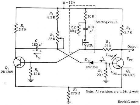
Designed to switch 4-mct load having 12.v supply. Output is -12 v for period that can be adjusted from. 1 to 5 sec. Timing is accurate within 10 from -20 to +60℃.-Texas Instruments Inc., Transistor Circuit Design, McGrctw4iill, N.Y., 1963, p 413. (View)
View full Circuit Diagram | Comments | Reading(655)
VOLTAGE_REGULATOR
Published:2009/7/5 21:21:00 Author:May

View full Circuit Diagram | Comments | Reading(2221)
HT6337 (electric fan) infrared remote control receiving decoder circuit
Published:2011/8/1 3:42:00 Author:Christina | Keyword: electric fan, infrared, remote control, receiving, decoder
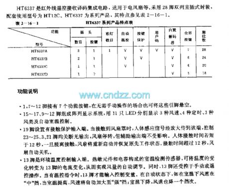


The HT6337 is designed as one kind of infrared remote control receiving decoder circuit that can be used in the electric fan application. It uses the 28-pin dual-row DIP package, the matching model is HT12C. The HT6337 is one of the series products. The features of it are as shown in table 2-16-1.
The pin-1, pin-7 - pin-12 have the function buttons.The array display system is composed of the 15-17,9-12 pins, and the system uses 11 LEDs to display three kinds of wind velocities, four kinds of timings, three kinds of wind types and the automatic room temperature control.The 19-pin has the contact protection input port.The 13-pin is the environmental temperature control input port. The room temperature detection sensor is composed of the thermal components and the capacitances, it can change the temperature variation into the current variation of pin-13.
(View)
View full Circuit Diagram | Comments | Reading(3372)
EEPROM_VSUBPP_SUB_pulse_generator
Published:2009/7/23 22:12:00 Author:Jessie

This circuit is similar to that for flash memories (Figs. 6-48, 6-49, and 6-50), but is designed specifically for EEPROMS. (View)
View full Circuit Diagram | Comments | Reading(738)
FM_demodulator
Published:2009/7/23 22:12:00 Author:Jessie

This circuit shows a precision PLL connected as an FM demodulator.The circuit can be tailored to any FM demodulation application by a choice of external components. For example, to demodulate an FM signal with a 67-kHz carrier and ±5 kHz deviation, use the following components: CO=746 pF,R1= 89.4 kΩ, C1=186 pF, RF=100 kΩ, and RC=80.6 kΩ, RO=20 kΩ. Use an 18-kΩ fixed resistor and a 5-kΩ potentiometer for RO and RX. Fine tune the circuit with RX. (View)
View full Circuit Diagram | Comments | Reading(3)
TRANSFORMERLESS_TONE_ANNUNCIATOR
Published:2009/7/5 21:21:00 Author:May

This circuit does not require an output transformer or an output coupling capacitor;the annunciator can easily be turned on or off by a control input voltage driving a 10-MΩ input resistor, R3. For a smaller acoustic output, replace output transistor, Q1, with a 100-Ω resistor, while also raising the voice coil impedance to 100Ω, to prevent loading of the IC. (View)
View full Circuit Diagram | Comments | Reading(1276)
DC_MOTOR_CONTROL
Published:2009/7/5 21:21:00 Author:May

Developed for use in realistic Iunar lander simulation display. Throttle signal and altitude signal serve as inputs to microprocessor. Feedback position-measuring pot is geared to 12-VDC motor so fuil travel of pot shaft occurs while lunar module traverses full altitude range. Circuit provides minimum drive voltage required by DC motor for motion to occur. Output of difference amplifier IC1 goes to summing amplifier IC4 as one component of final motor voltage. Comparators IC2 and IC3 sense when difference voltage is larger than small positive voltage set by R13 or smallerthan small negative voltage set by R14. Comparator output then becomes 12 V, and portion of this (about 2 V) drives motor into operating range.IC5 is high-power opamp delivering 1 A at 12 V.-L. Sweer,T. Dwyer, and M. Critchfield, Controlling Small DC Motors with Analog Signals, BYTE, Aug. 1977, p 18-20, 22, and 24. (View)
View full Circuit Diagram | Comments | Reading(2025)
REPEAT_CYCLE_TIMER
Published:2009/7/23 22:12:00 Author:Jessie
Provides output pulses over dynamic range of several thousand. Will tolerate large ripple from power source. If D4, D5, and C4 are added as shown in darted lines, will tolerate transients up to 100% of supply voltage with several microsec duration.-Low-Frequency Stairstep Generator and Timing Circuit, Electronic Circuit Design Handbook, Mactier Pub. Corp., N.Y., 1965, p 144. (View)
View full Circuit Diagram | Comments | Reading(1051)
SCR_PREREGULATOR_FITS_ANY_POWER_SUPPLY
Published:2009/7/5 21:20:00 Author:May

Circuit Notes
This SCR pre-regulator keeps the filter capacitor Vc, in a variable output power supply, a few volts above the output voltage Vo. The benefits include: less heat dissipated by the pass transistor and therefore small heatsink, cooler operation and higher efficiency, especially at low output voltages.Q1, R1, R2, D1 and D2 form a constant current source for zener Z1, so that the contribution to the output current is always a few mA (2-3 mA).The Darlington pair Q2, Q3 keeps the SCR off. The voltage Vcdecreases until Vc= Vo=V at which point the Darlington pair fires the SCR, charging the filter capacitor to a higher voltage Vc1 in less than half the period of the input voltage. The component values, shown are for a 0-250-V, 3-A power supply. (View)
View full Circuit Diagram | Comments | Reading(5565)
SATURABLE_REACTOR_TIMER
Published:2009/7/23 22:11:00 Author:Jessie
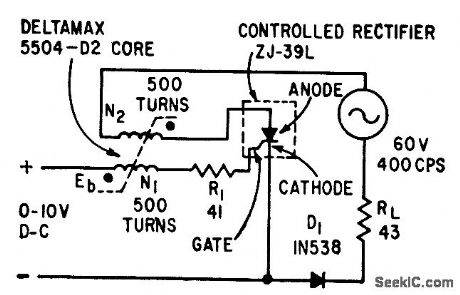
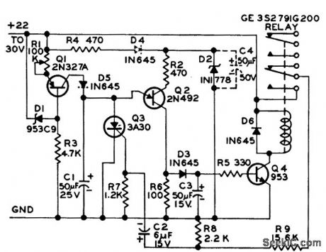
Varying d-c bias voltage applied to control winding or saturable reactor changes time for magnetic flux to reach final value, permitting use of circuit us frequency divider for timing applications. In 400-cps circuit shown, division can be adjusted over range front 1 to 10. Output diode prevents thermal runaway in controlled rectifier when anode is going negative and gate is positive to cathode.-J. S. Sicko, Counting and Timing Circuits Use Saturable Reactor, Electronics, 33:19, p 61-63. (View)
View full Circuit Diagram | Comments | Reading(1089)
1_kHz_L0W_DISTORTlON
Published:2009/7/5 21:19:00 Author:May
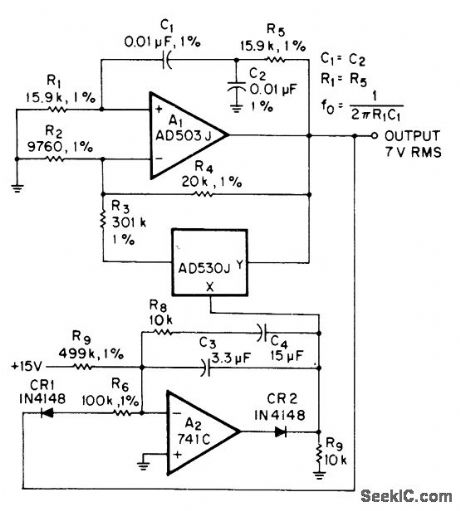
Total harrnonic distortion is only 0.01% in amplitude-stabilized oscillator delivering 7 VRMS. Opamp A1 has closed-loop gain of 3. Regenerative feedback through bandpass filter C1-C2-R1-R5 determines frequency of oscillation. Output is stabilized by multiplier whose control voltage is derived from integrator A2.-R. Burwen. Ultra Low Distortlon Oscillator. EDN/EEE Magazine. June 1. 1971. p 45. (View)
View full Circuit Diagram | Comments | Reading(426)
HD44043 (TV) infrared remote control receiving decoder circuit
Published:2011/8/1 3:22:00 Author:Christina | Keyword: TV, infrared, remote control, receiving, decoder circuit


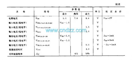
The HD44043 is designed as one kind of infrared remote control receiving decoder circuit that can be used in the TV application. The internal circuit is composed of the wave-detector, the signal discrimination circuit, the data decoding circuit, the timing decoding circuit, the channel-selection controller, the oscillator, the reset circuit and the output circuit.
Features
It uses the CMOS technology.Low power consumption, the typical value is 5.5mW.It can receive 31 kinds of instructions.It can input the volume up/down and the power switching instructions directly.The D/A output control has 32 stages.The HD44043 can be used with the preamplifier integrated circuit HD44042 to reduce the peripheral ICs.The HD44043 can be used with the channel-selection IC HD38986 to select the channel directly.
(View)
View full Circuit Diagram | Comments | Reading(1139)
HALF_FLASH_ADC
Published:2009/7/5 21:17:00 Author:May


An a/d conversion technique which combines some of the speed advantages of flash conversion with the circuitry savings of successive approximation is termed half-flash. In an 8-bit, half-flash converter, two 4-bit flash a/d sections are combined. The upper flash a/d compares the input signal to the reference and generates the upper 4 data bits. This data goes to an internal DAC, whose output is subtracted from the analog input. Then, the difference can be measured by the second flash a/d, which provides the lower 4 data bits. (View)
View full Circuit Diagram | Comments | Reading(2436)
MOVING_LIGHT_DISPLAY
Published:2009/7/5 21:16:00 Author:May

Computer-controlled blinking of LEDs arranged in circle or other pattern gives illusion of motion. One section of quad 7475 latch is assigned to each of several output ports of microprocessor. Decoding logic of output port determines when latch is addressed for output. Decoded WRITE signal latches data presented at bus receivers. lnterface can be extended to many registers in groups of eight, limited only by input/output addressing capability and power available for LEDs. Software is written to turn on LEDs in desired sequence and provide desired variable delays between blinks.-C. Helmers, There's More to Blinking Lights than Meets the Eye, BYTE, Jan. 1976, p 52-54. (View)
View full Circuit Diagram | Comments | Reading(2222)
PROGRAMMED_BIT_RATES
Published:2009/7/5 21:12:00 Author:May
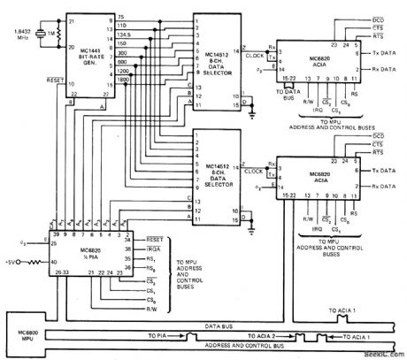
Choice of 37 differentbit rates in rangefrom 75 to 1800 b/s, each multiplied by 1, 8, 16, or 64, can be obtained from Motorola MC1441 bit-rate generator, two 8-channel data selectors, half of peripheral interface adapter (PIA) and two asynchronous communication interface adapters (ACIA) by appropriate programming of Motorola MC6800 microprocessor used in data communication system. Article gives operating details and example of Initialization program,-C,Nash,Microprocessor Software Programs Bit-Rate Generator,EDN Magazine.Aug 20.1977.p134.136.and 137. (View)
View full Circuit Diagram | Comments | Reading(1124)
HD44042 (TV) infrared remote control receiving preamplifier circuit
Published:2011/8/1 3:03:00 Author:Christina | Keyword: TV, infrared, remote control, receiving, preamplifier circuit
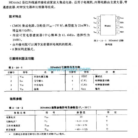
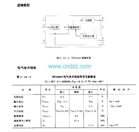
The HD44042 is designed as the infrared remote control receiving preamplifier circuit that can be used in the TV application. The internal circuit is composed of the main amplifier, bandpass filter, clock generator and the comparator.
Features
It uses the CMOS integrated circuit, the power consumption is low (when the VDD=7V, the typical value is 21mW), the gain is high (92dB).It has the variable capacity filter (the center frequency is 41.4kHz, the gain is 10dB).The external resistance can change the distance between the transmitter and the television.8-pin dual-row DIP package.
(View)
View full Circuit Diagram | Comments | Reading(627)
| Pages:1089/2234 At 2010811082108310841085108610871088108910901091109210931094109510961097109810991100Under 20 |
Circuit Categories
power supply circuit
Amplifier Circuit
Basic Circuit
LED and Light Circuit
Sensor Circuit
Signal Processing
Electrical Equipment Circuit
Control Circuit
Remote Control Circuit
A/D-D/A Converter Circuit
Audio Circuit
Measuring and Test Circuit
Communication Circuit
Computer-Related Circuit
555 Circuit
Automotive Circuit
Repairing Circuit