
Circuit Diagram
Index 1085
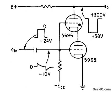
SYNCHRONOUS_SAMPLER
Published:2009/7/23 22:00:00 Author:Jessie

Time jitter of digital receiver output pulse is eliminated by synchronous sampling of detected signal. Each bit is sampled by local clock pulses that trigger flip-flop Q1-Q2. Two outputs of slicer, 180° out of phase, are applied to bases of Q1 and Q2. Output of flip-lop is regenerated information, free of jitter.-J. L. Hollis, Sending Digital Data Over Narrow. Band Lines, Electronics, 32:23, p 72-74. (View)
View full Circuit Diagram | Comments | Reading(490)
DIAL_TELEPHONE_TESTER
Published:2009/7/23 21:59:00 Author:Jessie
Delivers large pulses without being sensitive to changes in load, through use of thyratron in flip-flop.- thyratron Used for Bistable Circuit, Electronics, 32:6, p 64-65. (View)
View full Circuit Diagram | Comments | Reading(617)
10_Hz_WIEN_BRIDGE
Published:2009/7/5 21:54:00 Author:May
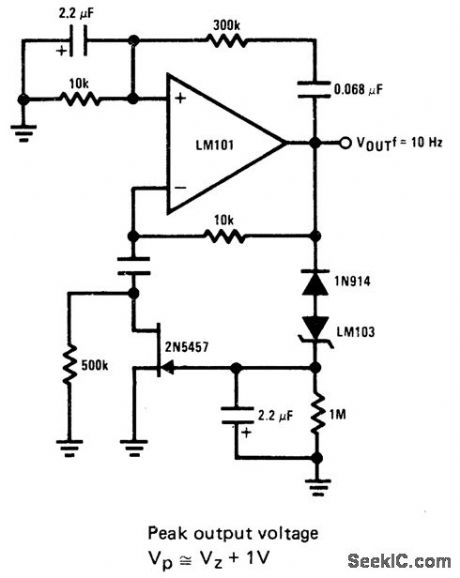
JFET serves as voltage-variable resistor in feedback loop of opamp. as required for producing low-distortion constant amplitude sine wave LM 103 zener providrs voltage for peak amplitude of sine wave this voltage is rectified and fed to gate of JFET to vary its channel resistance and loop gain of opamp.- FET Databook, National Semiconductor. Santa Clara. CA. 1977. p 6-26-6-63 (View)
View full Circuit Diagram | Comments | Reading(827)
Interfacing_D_A_converters_with_CMOS_and_ECL
Published:2009/7/23 21:59:00 Author:Jessie
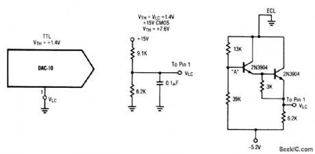
This circuit shows the interface circuits that are required to interface atypical TTL DAC (or similar IC) with ECL and CMOS digital devices. Note that HTL, PMOS, and NMOS devices can generally be interfaced with the CMOS circuit. (View)
View full Circuit Diagram | Comments | Reading(591)
HYDROPHONE_PREAMPLIFIER
Published:2009/7/23 21:59:00 Author:Jessie
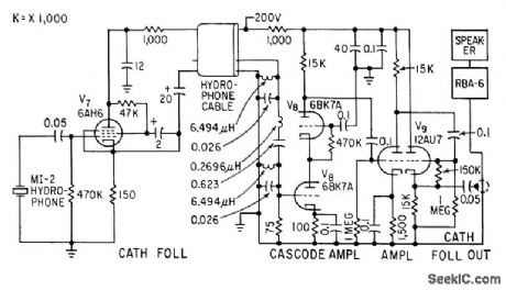
Cathode-follower hydrophone isolation amplifier and high-gain preamplifier feed Navy RBA-6 low-frequency radio receiver on trawler, to receive modulated 21-kc beam that transmits trawl net depth data.-F. H. Stephens, Jr., Underwater Telemeter for Trawl Fishing, Electronics, 32:13, p 66-68. (View)
View full Circuit Diagram | Comments | Reading(805)
PICTURE_DRAWING_LIGHT_PEN
Published:2009/7/5 21:54:00 Author:May
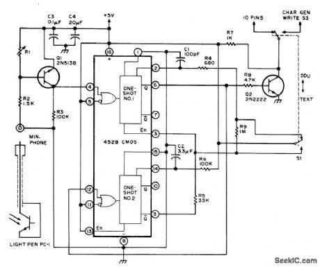
Circuit improves ability to draw pictures on display screen with light pen by using short data lockout period to avoid smearing. Value of R1 depends on light pen; use 1 megohm for Texas lnstruments H-35. One-shot No. 1 produces constant-amplitude 200-ns pulse for storing 1 or 0 bit in 2102 memory of CRO graphics interface, One-shot No. 2 delays generation of another write command 0.25 s, giving operator time to withdraw or move pen before double dot is formed. R4 and C1 control length of writepulse, while R5 and C2 control wait time.-S. S.Loomis, Let There Be Light Pens, BYTE, Jan.1976, p 26-30. (View)
View full Circuit Diagram | Comments | Reading(1096)
MOTORT_TACHOMETER_SPEED_CONTROL
Published:2009/7/5 21:53:00 Author:May

The tachometer, on the same shaft as the dc motor, is simply a generator. It gives a dc output voltage proportional to the speed of the motor. A summing amplifier, A1, controls its output so that the tachometer voltage equals the input voltage, but of opposite sign. With current drive to the motor, phase lag to the tachometer is 90°, before the second order effects come in. Compensation on A1 is designed to give less than 90° phase shift over the range of frequencies where the servo loop goes through unity gain.
Should response time be of less concern, a power op amp could be substituted for A1 to drive the motor directly. Lowering break frequencies of the compensation would, of course, be necessary. The circuit could also be used as a position servo. All that is needed is a voltage indicating the sense and magnitude of the motor shaft displacement from a desired position. This error signal is connected to the input, and the servo works to make it zero. The tachometer is still required to develop a phase-correcting rate signal because the error signal lags the motor drive by 180°. (View)
View full Circuit Diagram | Comments | Reading(1236)
High_performance_mtxer
Published:2009/7/23 21:59:00 Author:Jessie
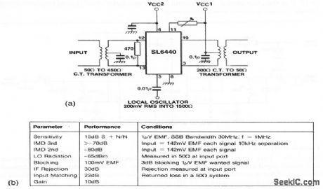
This circuit shows an SL6440 (Fig. 2-10) mixer with transformer coupling. Figure 2-20B shows the circuit characteristics. (View)
View full Circuit Diagram | Comments | Reading(1127)
Break_before_make_delay
Published:2009/7/23 21:58:00 Author:Jessie
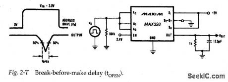
Figure 2-T shows a test circuit for measuring break-before-make delay for the MAX328/29, Again, a pulse is required at the analog inputs. Typical break-before-make delay is 0.2 μps. (View)
View full Circuit Diagram | Comments | Reading(794)
Access_time_tests
Published:2009/7/23 21:58:00 Author:Jessie

Figure 2-S shows a test circuit for measuring access time versus logic level (high) for the MAX328/29. Notice that a pulse signal is required at the analog inputs.
Typical access time (or transition time) for the MAX328/39M is 1μs maximum, with 1.5μs maximum for the MAX328/29C/E. (View)
View full Circuit Diagram | Comments | Reading(529)
D_A_converter_with_bipolar_output
Published:2009/7/23 21:58:00 Author:Jessie
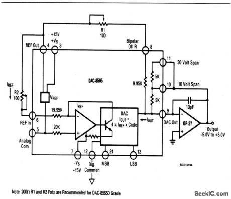
This circuit shows a DAC/op-amp combination that is used to provide ±5-V, ±10-V, or ±2.5-V bipolar outputs, with positive full-scale occurring when all bits are on (all 1s). To calibrate, turn off all bits, adjust R1 for -5.000, -10.000 or -2.500 V, depending on the range. If a precision op amp, such as the OP-27, OP-7, or OP-37 is used, no separate trimming of the op amp is required or recommended. (View)
View full Circuit Diagram | Comments | Reading(451)
Tuned_amplifier_CM_pinout
Published:2009/7/23 21:57:00 Author:Jessie
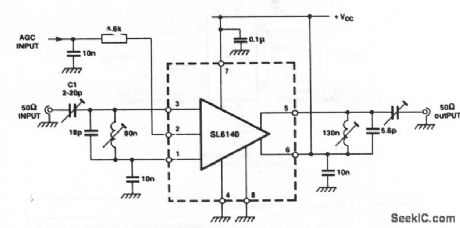
This circuit shows an SL6140 connected as a single-ended amplifier with tuned input and output networks (Fig. 2-40). The bandwidth and gain depend on the Q of the tuned/matching circuits. Using the values shown, the bandwidth is 100 MHz, with a power gain of 35 dB. (View)
View full Circuit Diagram | Comments | Reading(573)
Photodiode_amplifier_1
Published:2009/7/23 21:57:00 Author:Jessie
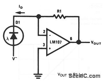
As shown by the equation,VOUT depends on photodiode current and R1 (which should be chosen for range or scale factor). (View)
View full Circuit Diagram | Comments | Reading(499)
Gentleman E1080PK Decoding Power Amplifier Upgrading Circuit
Published:2011/7/26 21:11:00 Author:Robert | Keyword: Gentleman, Decoding, Power Amplifier, Upgrading

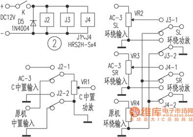
The picture shows the Gentleman E1080PK decoding power amplifier upgrading circuit.
1.In the original device the middle power amplifier and the surrounding power amplifier have the same principle which are installed on a same circuit board (which is shown in the picture). The difference is the surrounding power amplifier's negative feed-back resistance R60 is 150kΩ. So it should also change the feed-back resistance R503 to 150kΩ in the middle power amplifier to make the dual sound-channels' gain be same. The original device's middle power amplifier would be used as another sound-channel surrounding power amplifier. And also it should make the original device's four surrounding wiring terminals's series terminals be disconnected and then connect them to the dual channel surrounding power amplifier's output ports. (View)
View full Circuit Diagram | Comments | Reading(420)
SIGNAL_SEEKING_TUNER
Published:2009/7/23 21:57:00 Author:Jessie

Three silicon diodes, whose capacitances can be varied with externally applied bias voltages, replace conventional tuning capacitors.-J. G. Hammer-slag, Signal-Seeking Auto Radio Uses Semiconductor Tuning, Electronics, 33:30, p 60-62. (View)
View full Circuit Diagram | Comments | Reading(608)
RELAY_TESTER
Published:2009/7/23 21:57:00 Author:Jessie

Up to 30 relays ore cycled automatically for minutes or hours to break in contacts and show up early defects. Tester stops and holds for intermittent con tact fault, and lights lamp to identify faulty contact.-F. Trainor, Automatic Relay Tester Delects Infermittents, Electronics, 33:50, 79-81. (View)
View full Circuit Diagram | Comments | Reading(1483)
OTL Power Amplifier Principle Circuit
Published:2011/7/29 18:41:00 Author:Robert | Keyword: OTL, Power, Amplifier, Principle

2.The analysis for otl power amplifier principle.
The features of the otl power amplifier are listed here.
(1)When static there is no current through RL.
(2)D1, D2 or R, or R, D, would supply the T1, T2 two transistors a certain positive bias voltage to make them in micro-conduction mode, which means working in class AB.
(3)RC3 is T3's collector polar's load resistance. b1, b2 these two points' voltage difference is about 1.4V all the way. But their AC voltage's variation values are the same.
(4)When it only needs a single power and it also adds a capacitor C, the selection of C should meet:C should be large enough (larger than Vi's maximum cycle time) to make Vc=0.5Vcc.
(5)T3's bias voltage is get from the K point. It has the function that make the Q point stable automatically and it could adjust the Vk by adjusting R2. (View)
View full Circuit Diagram | Comments | Reading(428)
Two Kinds Of Heat Preservation Type Automatic Electric Pressure Cooker Principle And Repairing Circuit
Published:2011/7/29 6:40:00 Author:Robert | Keyword: Heat Preservation, Automatic, Electric, Pressure Cooker, Principle, Repairing

The picture shows the two kinds of heat preservation type automatic electric pressure cooker principle and repairing circuit.
1.Yongxing brand DYB50-100 type electric pressure cooker.(1)The principle of the circuit.The circuit is shown in picture 1. When it connects the power supply, clockwise rotating the timer (electric type) PT to an adequate pressure-keeping stage, and the PT contactor would be closed. So the 220V AC power would be added on the main heating loop circuit which is composed of heating temperature control device ST1, heat preservation temperature control device ST2, main heater EH1, over-heat fuse FU and so on. When the heating indication lamp HL1 is bright, the EH1 would heat and the temperature in the cooker would increase. When it gets to working pressure 85kPa, ST2, ST1 would be disconnected separately to disconnect the main heating loop circuit's power source. The HL1 would be off and the EH1 would stop heating. At this time the pressure-keeping loop circuit, which is composed of pressure-keeping heating device EH2, PT, EH1 and FU, would heat. (View)
View full Circuit Diagram | Comments | Reading(3334)
Data_acquisition_front_end
Published:2009/7/23 22:08:00 Author:Jessie

Figure 2-1 shows a typical data0acquisition system using a MAX358 multiplexer.Because the mux is driving a high-impedance input , the error is a function of IC resistance r DS(ON) times the mux leakage current I DS(ON) and the amplifier bias current IBIAS、or:VBRROR=r DS(ON) ×I D(ON) +IBIAS(MAX420) =1.5kΩ×(2nA+30 pA) =3.05-μV maximum error (View)
View full Circuit Diagram | Comments | Reading(568)
Serially_programmable_VHF_frequency_synthesizer
Published:2009/7/23 22:15:00 Author:Jessie

This circuit uses an NJ8822 single-chip synthesizer, an SP8793 dual-modulus prescaler, and an SL562 op amp. The VCO is a JFET oscillator that uses a transmission line as the resonator. This VCO is modulated by applying the audio signal to the cathode of a reverse-biased PIN diode, as shown in the circuit diagram. The loop filter uses the SL562, which (with the values shown) has a loop bandwidth of 60 Hz and a damping factor of 0.6. This filter is followed by a low-pass pole at 3.7 kHz to attenuate the 12.5-kHz reference sidebands. The lock-up time for a 1-MHz change in frequency is 80 ms. The output frequency range is 144 to 146 MHz and the level is +3 dB into 50Ω. (View)
View full Circuit Diagram | Comments | Reading(2972)
| Pages:1085/2234 At 2010811082108310841085108610871088108910901091109210931094109510961097109810991100Under 20 |
Circuit Categories
power supply circuit
Amplifier Circuit
Basic Circuit
LED and Light Circuit
Sensor Circuit
Signal Processing
Electrical Equipment Circuit
Control Circuit
Remote Control Circuit
A/D-D/A Converter Circuit
Audio Circuit
Measuring and Test Circuit
Communication Circuit
Computer-Related Circuit
555 Circuit
Automotive Circuit
Repairing Circuit