Basic Circuit
Homemade wireless video doorbell circuit
Published:2011/7/26 2:14:00 Author:Christina | Keyword: Homemade, wireless, video doorbell | From:SeekIC


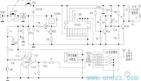
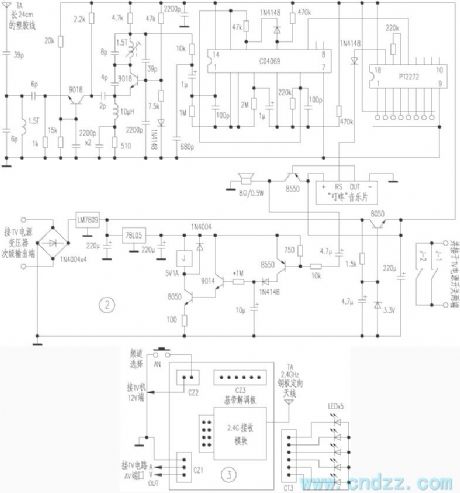
Figure 1 is the outdoor circuit, AN1 and AN2 are the buttons of the doorbell, when the guest presses the button of the doorbell, one channel of the power supply supplies the power to the coding launch circuit through the AN2, the coding launch circuit outputs the 315MHz coded signal, at the same time the power supply charges the 10μF timing capacitor through 1N4148. Another channel of the power supply supplies the power to the delay circuit through the AN1, the relay gets power to close, the contact point J-1 closes to protect itself. And the LM386 forms the voice pick-up circuit, the video camera and the 2.4GHz transmitter module all get power to work, the transmitter module outputs the high frequency signal which is modulated by the AV signal.
Reprinted Url Of This Article:
http://www.seekic.com/circuit_diagram/Basic_Circuit/Homemade_wireless_video_doorbell_circuit.html
Print this Page | Comments | Reading(3)

Article Categories
power supply circuit
Amplifier Circuit
Basic Circuit
LED and Light Circuit
Sensor Circuit
Signal Processing
Electrical Equipment Circuit
Control Circuit
Remote Control Circuit
A/D-D/A Converter Circuit
Audio Circuit
Measuring and Test Circuit
Communication Circuit
Computer-Related Circuit
555 Circuit
Automotive Circuit
Repairing Circuit
Code: