Electrical Equipment Circuit
Charge_injection_tests
Published:2009/7/23 22:05:00 Author:Jessie | From:SeekIC

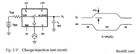
Figure 2-V shows a test circuit for measuring charge injection for the MAX301/ 3/5. Notice that charge injection (Q) is measured in coulombs (C). A pulse is applied to the control pin and the difference in output voltage is noted. Q is calculated when the difference in output voltage is divided by the capacitance at the output. Typical charge injection is 10 to 15pC.
Reprinted Url Of This Article:
http://www.seekic.com/circuit_diagram/Electrical_Equipment_Circuit/Charge_injection_tests.html
Print this Page | Comments | Reading(3)

Article Categories
power supply circuit
Amplifier Circuit
Basic Circuit
LED and Light Circuit
Sensor Circuit
Signal Processing
Electrical Equipment Circuit
Control Circuit
Remote Control Circuit
A/D-D/A Converter Circuit
Audio Circuit
Measuring and Test Circuit
Communication Circuit
Computer-Related Circuit
555 Circuit
Automotive Circuit
Repairing Circuit
Code: