
Circuit Diagram
Index 867
107_MHz_FM_IF_amplifier_and_detector_using_four_ECG1104_5_pin_modules
Published:2009/7/20 2:40:00 Author:Jessie
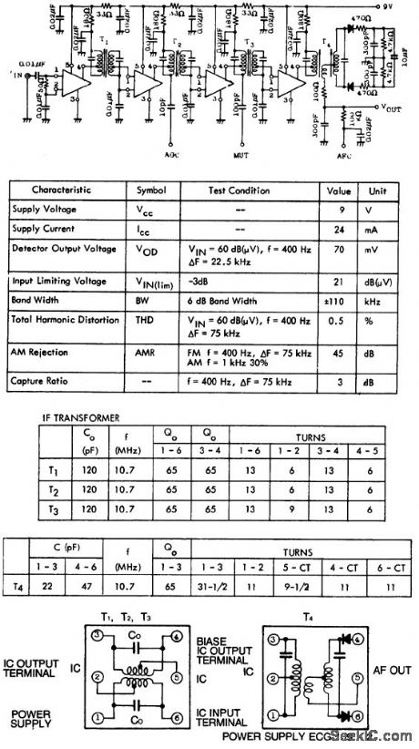
10.7 MHz FM IF amplifier and detector using four ECG1104 5-pin modules. Coil data and specifications also are shown (courtesy GTE Sylvania Incorporated). (View)
View full Circuit Diagram | Comments | Reading(591)
FORMING_ELECTROLYTICS
Published:2009/7/20 2:40:00 Author:Jessie
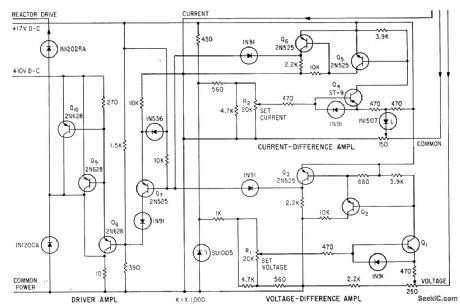
Current-difference amplifier delivers constant current during initial forming of electrolytic capacitors, and voltage-difference amplifier holds voltage constant when final forming voltage is reached. Values of current and voltage can be adjusted over wide range of preset values for different sizes of capacitors.-J. W. Martin and H. Liepins, Unique Power Supply. Delivers Constant Voltage and Current, Electronics, 35:31, p 40-41. (View)
View full Circuit Diagram | Comments | Reading(748)
POSITIONING_AND_ATTENUATING_CONTROL
Published:2009/7/20 1:59:00 Author:Jessie
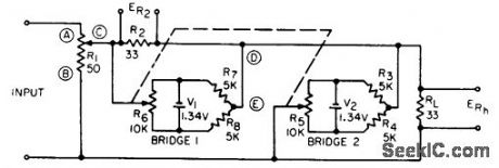
Adds d-c positioning voltage lo input signal of recording galvanometer. Magnitudes of input and positioning voltages can be varied independently without interaction. Circuit also has attenuating control for signal voltage.-N. Kassowitz, Non-Interacting Positioning and Attenuating Controls, EEE, 13:3, p 47. (View)
View full Circuit Diagram | Comments | Reading(506)
The thickness of the paper detector
Published:2011/7/21 22:30:00 Author:qqtang | Keyword: detector, thickness
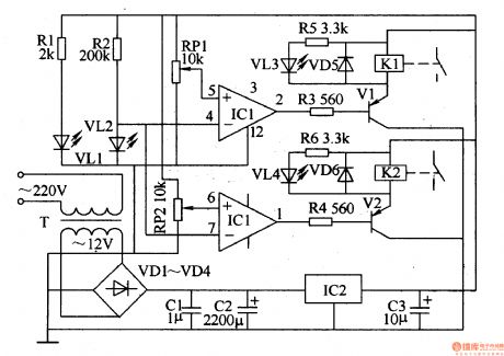
The working principle of the circuitThe thickness of the paper detector circuit consists of the power supply circuit, infrared detection circuit and control executing circuit, see as figure 8-143.
The power supply circuit consists of the power supply transformer T, rectifier diode VD1-VD4, filter capacitor C1-C3 and 3-terminal regulator IC2 and so on.The AC 220V current is stepped down by T, rectified by VD1-VD4, stabilized by IC2 and filtered by C1-C3, then it becomes a 12V DC voltage and it is provided for the infrared detection circuit and control executing circuit.
(View)
View full Circuit Diagram | Comments | Reading(981)
FET_HARTLEY
Published:2009/7/20 1:59:00 Author:Jessie
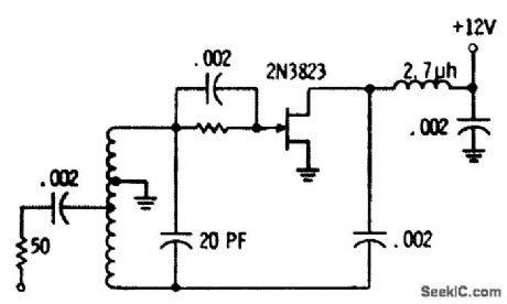
Delivers 680 mv to 50-ohm load at 100 Mc. Coil is four 3/8-inch-diameter turns of No. 16 wire spaced to 0.5 inch.-Fets Come Alive: Clinic Unveils Practical Circuits, EEE, 14:4, p 16-18. (View)
View full Circuit Diagram | Comments | Reading(892)
TONE_DECODER
Published:2009/7/20 1:57:00 Author:Jessie
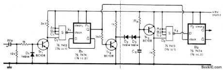
Replaces resonant reeds commonly used in multichannel radio-con-trolled models to detect modulation frequency being transmitted. Use of IC logic has advantage that range of audio frequencies can exceed an octave, whereas reeds cannot because they respond to second harmonic. Decoder has digital high-pass characteristic that is passed through inverter to give digital low-pass characteristic. Values of RX, and CX determine critical frequency; for 900 Hz, use 150,000 ohms and 0.015 μF. To obtain n nonoverlapping bandpass characteristics, n - 1 basic elements with different critical frequencies are required; components to left of dashed line may be common to all these elements. Article covers multichannel systems in detail, along with use of time-division multiplexing.-C. Attenborough, Radio Control Tone Decoder, Wireless World, Dec.1973, p 593-594. (View)
View full Circuit Diagram | Comments | Reading(2259)
AUTOMATIC_NULLING
Published:2009/7/9 23:05:00 Author:May
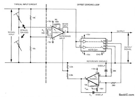
Simple offset zeroing loop reduces effective input offset of instrumentation amplifier to less than a microvolt by using zero-and-hold that nulls output of instrumentation opamp A1 to reference ground. Article describes operation in detail. Input signal source drives logic input, for nulling up to 4 V without using external nulling pot,.Typical input circuit using strain gages is shown at left of dashed line.-M. Cerat, Zeroing Loop Reduces Instrumentation Amplifier Offsets, EDN Magazine, March 20, 1976, p 100 and 102. (View)
View full Circuit Diagram | Comments | Reading(765)
TIMING_SIGNAL_PLAYBACK
Published:2009/7/20 1:56:00 Author:Jessie
Timing signals, recorded as 50-v negative pulses, each corresponding to an edge of original interval-timing pulse in biomedical experiments, are converted to original rectangular pulse by pulse amplifier and bistable circuit. Negative pulse change state of bistable, to reproduce original pulse at output.-G. Silverman, Modified Tape Recorder Stores Timing Signals, Electronics, 39:13, p 75-76. (View)
View full Circuit Diagram | Comments | Reading(533)
3_WAY_LIGHT_CONTROL
Published:2009/7/9 23:04:00 Author:May
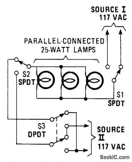

This hookup is useful in some house wiring situations, where only two wires are available between switches,rather than the 3-way setup where 3 wires are requires.S1 and S2 are ordinary three-way switches and S3,a DPDT switch,is commonly avaliable as a four-way switch at hardware stores. (View)
View full Circuit Diagram | Comments | Reading(704)
TWO_TONE_CONTROL
Published:2009/7/20 1:55:00 Author:Jessie
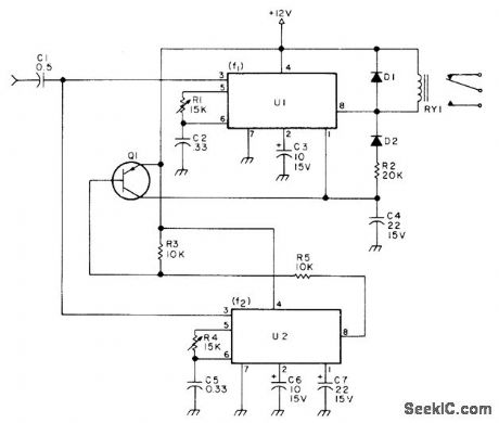
Used to perform simple ON/OFF auxiliary function via repeater input,Two 567 decoders energize relay for input tone of 1800Hz,with latching, and release it for 1950Hz Diodes are 1N4001,Relay can be 12 or24 V,al is 2N3905,2N3906,MPS6521,or 2N2222.-W Hosking. A Single Tone Can Do It,73Magazine, Nov 1977,p184-185 (View)
View full Circuit Diagram | Comments | Reading(723)
BIT_GRABBER
Published:2009/7/9 23:03:00 Author:May
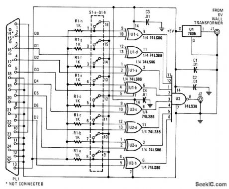
When the user set character (D0 through D7) from a computer matches the character programmed on SIA through S1A, the output from J2 becomes low. This device can be used as a test aid to check printer cable or as a control circuit for interfacing with a computer. (View)
View full Circuit Diagram | Comments | Reading(659)
UHF_TV_PREAMPLIFIER
Published:2009/7/9 23:03:00 Author:May
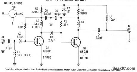
An inexpensive, antenna-mounted, UHF-TV preamplifter can add more than 25 dB of gain. The first stage of the preamp is biased for optimum noise, the second stage for optimum gain. L1, L2 strip line ≈λ/8 part of PC board. (View)
View full Circuit Diagram | Comments | Reading(5869)
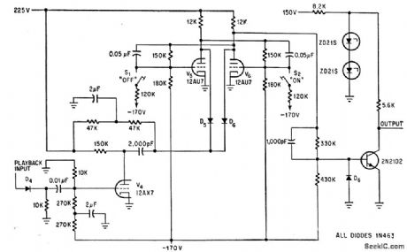
FACSIMILE_SYNC_PULSE_SHAPER
Published:2009/7/20 1:54:00 Author:Jessie
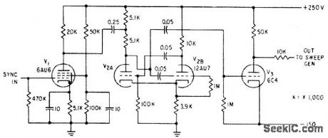
Used to change shape of high-precision sync pulse for facsimile recorder in order to change time of return trace. Amplifier V1 is coupled to plate driven one-shot mvbr whose time constants determine return trace time.-E. W. Winkle, High-Precision Sweep Generator, return trace. Amplifier V1 is coupled to plate. Electronics, 33:50, p 88-90. (View)
View full Circuit Diagram | Comments | Reading(570)
RS_232C_LINE_DRIVEN_CMOS_CIRCUITS
Published:2009/7/9 23:02:00 Author:May
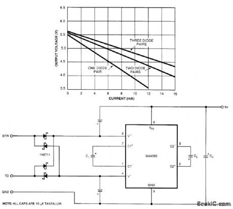
The circuit illustrates a way to power CMOS ICs from RS-232C lines. The MAX680 is normally used to generate a voltage eqqal to ±2 x VCC. This circuit does exactly the opposite. It takes in t 10.5 to ±12 V on the DTR and TD lines and puts out a 5.25- to 6-V signal. A pair of Schottky or silicon diodes rectifies each RS-232C line. The resultant energy is stored by the capacitors attached to the IC's V+ and V - pins. C1 or both C1 and C2 then reverse-charge pump the energy stored at the V+ and V- pins to C3. The input source current of the MAX680 is approximately equal to the voltage drop of any one of the diodes that is divided by the series resistance of 160Ω. When you drive this circuit from a 1488 driver with a ±12-V supply, it can deliver 5 V at 3 mA.
To increase the output current, you can use as many as three sets of diodes on each RS-242 line to provide 5 V at 8 mA. The more diodes you use, the lower the source resistance: RS equals the inversion of the sum of the diodes' conductances. If your circuit requires even more output current, you can place two MAX680s in parallel, tie their V + and V- capacitors together, and use separate C1 and C2 capacitors for each ship. If you do connect the devices in parallel, make sure not to exceed the power capability of the RS-232C lines. (View)
View full Circuit Diagram | Comments | Reading(758)
AUDIO_MILLIVOLTMETER_1
Published:2009/7/9 23:02:00 Author:May
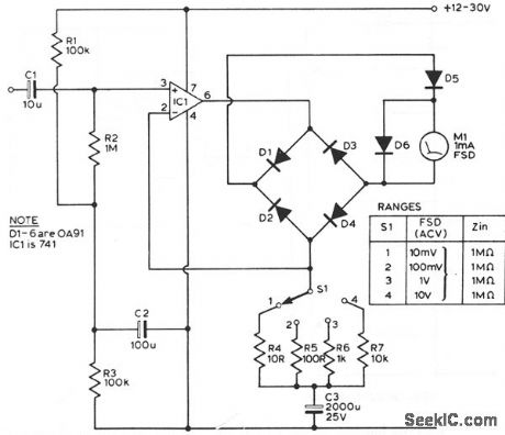
This circuit has a flat response from 8 Hz to 50 kHz at -3 db on the 10-mV range. The upper limit remains the same on the less sensitive ranges, but the lower frequency limit covers under 1 Hz. (View)
View full Circuit Diagram | Comments | Reading(1027)
FERRITE_BEAD_CURRENT_TRANSFORMER
Published:2009/7/9 23:01:00 Author:May
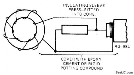
No. 27 ferrite bead (Ferronics 11-122-B) wound with 25 turns No. 30 enameled wire and shunted by 50-ohm1/4-W resistor, gives low-cost transformer that can be used in range of 3 kHz to 30 MHz. Current-conversion ratio is 1 V/A into 50-ohm coaxial-cable termination, with excellent linearity from milliamperes up into amperes. Wire carrying current to be measured is passed once through core, to serve as singleturn primary of transformer.-M. Salvati, Ferrite Bead Makes Cheap Current Transformer, EDN Magazine, March 20, 1974, p 85. (View)
View full Circuit Diagram | Comments | Reading(2287)
HALF_STEP_DRIVE_STEPPER_MOTOR
Published:2009/7/9 23:01:00 Author:May
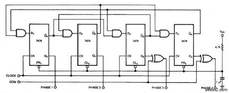
Clock pulses are converted to the switching sequence necessary for a four-phase stepper through 400 half steps of 0.9°each. (View)
View full Circuit Diagram | Comments | Reading(1525)
5_W_150_MHz_AMPLIFIER
Published:2009/7/9 23:00:00 Author:May
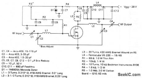
This circuit utilizes the MRF123 TMOS power FET The MRF134 is a very high gain FET that is potentially unstable at both VHF and UHF frequencies. Note that a 68-Ω input loading resistor has been utilized to enhance stability. This amplifter has a gain of 14 dB and a drain efficiency of 55%. (View)
View full Circuit Diagram | Comments | Reading(749)
500_Hz_CONTROL_TONE
Published:2009/7/20 1:53:00 Author:Jessie
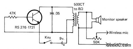
Developed for use as wireless FM remote control for keying transmitter at another location by sending keyed audio tone over radio link, acoustic link fed by loudspeaker, or audio line. Frequency is about 500 Hz.-J. Schultz, H.F, Operating-Remote Control Style, CQ, March 1978, p 22-23 and 90. (View)
View full Circuit Diagram | Comments | Reading(579)
LIGHT_CHASER_I
Published:2009/7/9 23:00:00 Author:May
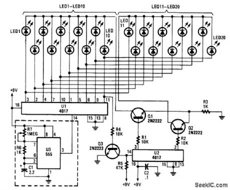
Up to 100 lights,LEDs,or optocoupler triac circuits can be sequentially activated by this circuit,One(U1)4017 decode counter sequences 10 LEDs whose common anode is returned through a second (U2) CD4017,which counts at one-tenth of the rate.The flash rate IS controlled by U3,a clock circuit,with a 555 timer. (View)
View full Circuit Diagram | Comments | Reading(3452)
| Pages:867/2234 At 20861862863864865866867868869870871872873874875876877878879880Under 20 |
Circuit Categories
power supply circuit
Amplifier Circuit
Basic Circuit
LED and Light Circuit
Sensor Circuit
Signal Processing
Electrical Equipment Circuit
Control Circuit
Remote Control Circuit
A/D-D/A Converter Circuit
Audio Circuit
Measuring and Test Circuit
Communication Circuit
Computer-Related Circuit
555 Circuit
Automotive Circuit
Repairing Circuit