
Circuit Diagram
Index 866
LIGHT_CONTROLLER
Published:2009/7/9 23:09:00 Author:May
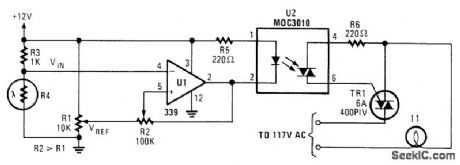
A photocell drives U1, acomparator, which controls optocoupler U2. A 6A Triac is used to switch an ac load,such a lamp,etc. (View)
View full Circuit Diagram | Comments | Reading(695)
The car distance audio reminder (2)
Published:2011/7/22 6:46:00 Author:qqtang | Keyword: audio reminder
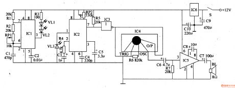
The working principle of the circuitThe car distance language reminder circuit consists of the power supply circuit, infrared emitter, infrared receiver and audio alarm circuit, see as figure 7-131.
The power supply circuit consists of ignite switch circuit, 3-phase regulated circuit IC6 and filter capacitors of C9 and C10. The infrared emitter consists of the relay R3, infrared LED of VL1 and VL2 and the 40khz multi-resonance oscillator circuit. The oscillator consists of the time-based integrated circuit IC1, resistors of R1 and R2, potentiometer RP1 and capacitors of C1 and C2 (View)
View full Circuit Diagram | Comments | Reading(448)
AM_broadcast_tuner_with_RF_amplifier_for_automobile_applicatio
Published:2009/7/20 2:44:00 Author:Jessie
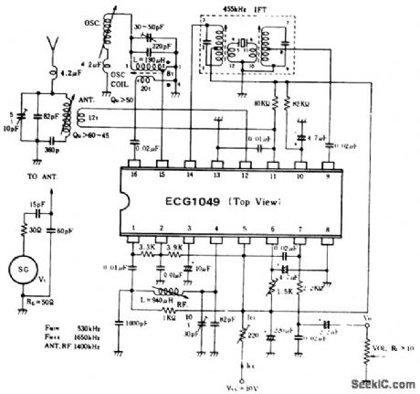
AM broadcast tuner with RF amplifier for automobile application. Audio output is 80 mV with 400-hertz modulation at 30%. The IF is 455 kHz. All coils and transformers are standard and can be purchased at Radio Shack (courtesy GTE Sylvania Incorporated). (View)
View full Circuit Diagram | Comments | Reading(691)
BASIC_TRACK_AND_HOLD_SAMPLE_AND_HOLD
Published:2009/7/9 23:09:00 Author:May
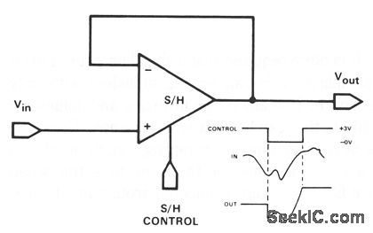
Feedback is the same as a conventional op-amp voltage follower which yields a unity-gain, noninverting output. This hookup also has a very high input impedance. The only difference between a track-and-hold and a sample-and-hold is the time period during which the switch is closed. In track-and-hold operation, the switch is closed for a relatively long period; the output signal might change appreciably and would hold the level present at the instant the switch is opened. In sample-and-ho1d operation, the switch is closed only for the time necessary to fully charge the holding capacitor. (View)
View full Circuit Diagram | Comments | Reading(994)
LIGHT_CHASER_II
Published:2009/7/9 23:08:00 Author:May
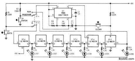
Up to six lights can be sequentially flashed using this circuit. LED1 through LED6 can be replaced by optocouplers (M0C3010, etc.) to control 120-Vac loads via triacs. U1 generates pulses that clock the shift register mode up of the six D flip-flops in the CD 40174. By S1A-B, the register can be programmed either ON or OFF (low or high) and then switched to nut in the programmed sequence. S2 clears the program. (View)
View full Circuit Diagram | Comments | Reading(2697)
MOTORCYCLE_TURN_SIGNAL_SYSTEM
Published:2009/7/20 2:43:00 Author:Jessie
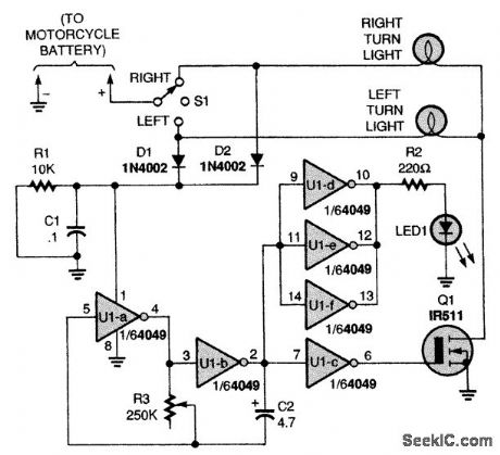
A low-frequency oscillator made up from a CMOS hex inverter drives an LED indicator and a power FET to act as a flasher. R3 and C2 control the flash rate. S1 controls L or R side lights for turnsignaling purposes. (View)
View full Circuit Diagram | Comments | Reading(0)
INTRUDER_ALARM
Published:2009/7/9 23:08:00 Author:May
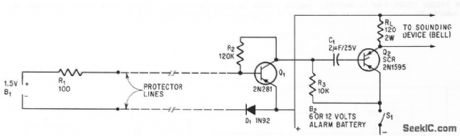
Circuit responds to break or short in loop of foil or wire encircling area to be protected, by reacting to change in normal current droin of 500 microamp from l.5.v battery in protector loop. Circuit is reset after alarm by opening SI1 momentarily,-W. Vollenweidel,Low-Current Alarm,Electronics,39:5,p 105-106.
(View)
View full Circuit Diagram | Comments | Reading(0)
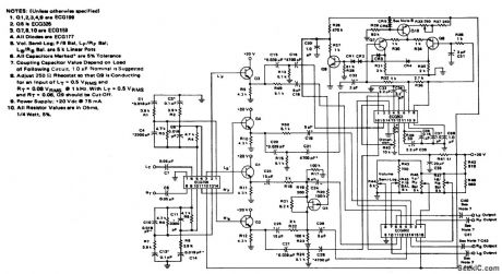
FM_IF_amplifier_and_discriminator_for_107_MHz_using_an_ECG760_Gain_is_typically_40_dB_at_107_MHz
Published:2009/7/20 2:43:00 Author:Jessie
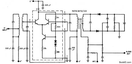
FM IF amplifier and discriminator for 10.7 MHz using an ECG760(enclosed in dashed lines)Gain is typically 40 dB at 10.7 MHz. Power supply voltage should be 20 volts(courtesy GTE Sylvania Incorporated). (View)
View full Circuit Diagram | Comments | Reading(575)
SAMPLE_AND_HOLD
Published:2009/7/9 23:07:00 Author:May
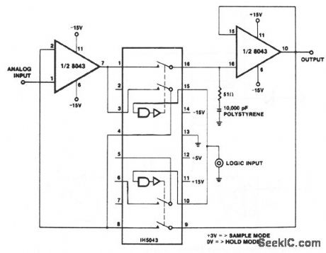
Two important properties of the 8043 are used to advantage in this circuit. The low input bias currents give rise to slow output decay rates (droop) in the hold mode, while the high slew rate at 6 V/μs improves the tracking speed and the response time of the circuit. The upper waveform is the input 10 V/div, the lower waveform the output 5 V/div. The logic input is high.The center waveform is the analog input, a ramp moving at about 67 V/ms, the lower waveform is the logic input to the sample-and-hold; a logic 1 initiates the sample mode. The upper waveform is the output, displaced by about one scope division 2 V from the input to avoid superimposing traces. The hold mode, during which the output remains constant, is clearly visible. At the beginning of a sample period, the output takes about 8 μs to catch up with the input, after which it tracks, until the next hold period. (View)
View full Circuit Diagram | Comments | Reading(0)
360_DEG_SHIFTER
Published:2009/7/20 2:42:00 Author:Jessie
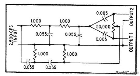
One variable component provides phase difference between outputs that is adjustable from -180 to +180 degrees without substantial change in magnitude, at fixed frequency of 2,500 cps,-W. Bacon, Circuit Shifts Phase 360 Degrees, Electronics, 31:23, p 94-97. (View)
View full Circuit Diagram | Comments | Reading(481)
SWITCH_BEBOUNCER
Published:2009/7/9 23:07:00 Author:May
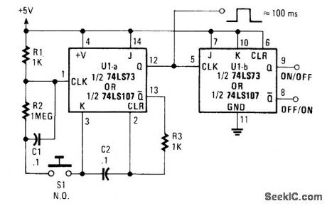
Using a 7473 JK flip-flop U1A connected as a monostable to drive U1B, as a switch debouncer. The circuit is self-clearing during power up. A 100-ms pulse is available at pin 12 U1A. (View)
View full Circuit Diagram | Comments | Reading(879)
LOW_VOLTAGE_INDICATOR
Published:2009/7/9 23:07:00 Author:May
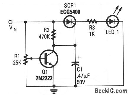
Input terminal VIN is connected to the + V line of the circuit that the indicator is to monitor, and the grounds of both circuits are connected together. The position of potentiometer R1's wiper deter-mines Q1's base voltage. As long as the transistor gets enough bias voltage to remain on, the low voltage at the collector will keep the SCR from firing. As the battery voltage starts to fall, the transistor's base voltage will fall as well. When Q1 turns off VIN drops), the collector voltage increases. That voltage provides enough gate drive to turn on the SCR, which turns on the LED. The LED could also be a buzzer or almost any other type of waming device. (View)
View full Circuit Diagram | Comments | Reading(1131)
4_channel_SQ_logic_decoder_1
Published:2009/7/20 2:42:00 Author:Jessie
4-channel SQ logic decoder. Current drain is 75 mA at 20 volts. Input impedance is 2M, while output impedance is 2K (courtesy GTE Sylvania Incorporated). (View)
View full Circuit Diagram | Comments | Reading(601)
POWER_FAILURE
Published:2009/7/9 23:06:00 Author:May
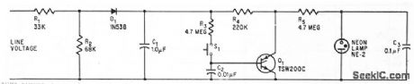
Current of 0.5 ma through R4 holds scr Q1 on normcdly. After power failure, scr will not fire again because it has no gate current. tine voltage across scr then makes neon relaxation oscillctor fiash warning signcal. Depressing S1 resets drcuit.-R.K. Honeycuff, SCR Monitors Electronics, 38:15, p 63. (View)
View full Circuit Diagram | Comments | Reading(623)
MOTORCYCLE_BURGLAR_ALARM
Published:2009/7/20 2:41:00 Author:Jessie
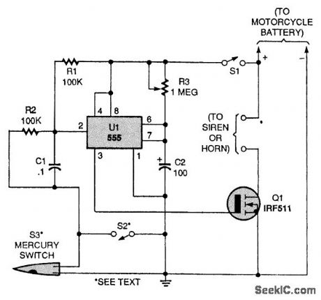
A 555 lC is connected in a one-shot timer circuit that turns on an FET and either a siren or the bike's horn for a preset time period. Switch S1 is used as an on/off switch. Closing either of two switches, S2 or S3, will trigger the IC. When either switch closes, pin 2 of U1 goes low. That triggers the IC to produce a positive output at pin 3 and sounds the alarm for the time period set by R3. The mercury switch, S3, is the switch that activates the alarm if someone moves your bike. Switch S2 can be used as a panic switch if you ever feel threatened. The IRF511 N-channel FET (Q1) will handle currents up to 4 A. If you need a higher-current device, an IRF530, which is rated at 14 A, can be substituted. (View)
View full Circuit Diagram | Comments | Reading(3546)
QUARTER_STEP_STEPPER_MOTOR_DRIVER
Published:2009/7/9 23:06:00 Author:May
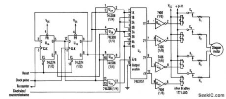
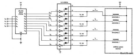
Using a counter and a PROM, this circuit drives the stepper windings with two levels of current. (View)
View full Circuit Diagram | Comments | Reading(811)
60_W_225-400_MHz_AMPLIFIER
Published:2009/7/9 23:06:00 Author:May
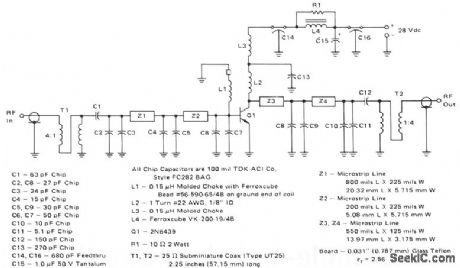
This 60-W, 28-V broadband amplifier covers the 225-400 MHz military communications band. The amplifier may be used singly as a 60-W output stage in a 225-400 MHz transmitter, or by using two of these amplifiers combined with quadrature couplers, a 100-W output amplifier stage can be constructed.The circuit is designed to be driven from a 50-Ω source and work into a nominal 50-Ω load. The input network consists of two microstrip L-sections composed of Z1, Z2, and C2 through CG. C1 serves as a dcblocking capacitor. A 4:1 impedance ratio coaxial transformer T1 completes the input matching network.L1 and a ferrite bead serve as a base decoupling choke. The output circuit consists of shunt inductor L2 at the collector, followed by two microstrip L-sections composed of Z3, Z4, and C8 through C11. C12 serves as a dc blocking capacitor, and is followed by another 4:1 impedance ratio coaxial transformer. Collector decoupling is accomplished through the use of L3, L4, C14, C15, C16, and R1. (View)
View full Circuit Diagram | Comments | Reading(735)
MEASURING_PHASE_UP_TO_400_MC
Published:2009/7/20 2:41:00 Author:Jessie
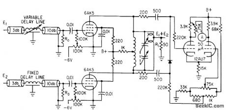
Three plug-in tuning circuits cover range from 15 to 400 Mc. Phase delay is compared with continuously variable delay standard with accuracy of 1% or 0.1°.-Y. P. Yu, How to Measure Phase at High Frequencies, Electronics, 34:11, p 54-56. (View)
View full Circuit Diagram | Comments | Reading(519)
05_watt_OTL_audio_power_amplifier_using_an_ECG1031
Published:2009/7/20 2:41:00 Author:Jessie
0.5-watt OTL audio power amplifier using an ECG1031. Typical voltage gain at 1 kHz is 50 dB. Input impedance is 20K (courtesy GTE Sylvania). (View)
View full Circuit Diagram | Comments | Reading(560)
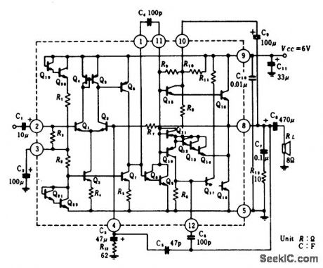
4_watt_audio_power_amplifier_with_a_7_mV_sensitivity_for_automobile_applications
Published:2009/7/20 2:40:00 Author:Jessie
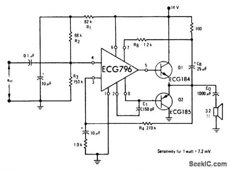
4-watt audio power amplifier with a 7 mV sensitivity for automobile applications. By changing the output transistors the output can be increased up to 20 watts (courtesy GTE Sylvania Incorporated). (View)
View full Circuit Diagram | Comments | Reading(630)
| Pages:866/2234 At 20861862863864865866867868869870871872873874875876877878879880Under 20 |
Circuit Categories
power supply circuit
Amplifier Circuit
Basic Circuit
LED and Light Circuit
Sensor Circuit
Signal Processing
Electrical Equipment Circuit
Control Circuit
Remote Control Circuit
A/D-D/A Converter Circuit
Audio Circuit
Measuring and Test Circuit
Communication Circuit
Computer-Related Circuit
555 Circuit
Automotive Circuit
Repairing Circuit