
Circuit Diagram
Index 881
Digital_gain_control_of_a_12_bit_successive_approximation_A_D_convener_using_an_AD559_8_bit_D_A_converter
Published:2009/7/20 4:05:00 Author:Jessie
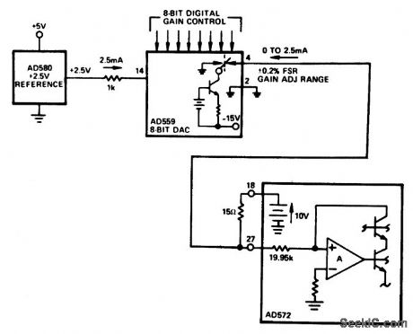
Digital gain control of a 12-bit successive approximation A/D convener (AD572) using an AD559 8-bit D/A converter (courtesy Analog Devices, Inc.). (View)
View full Circuit Diagram | Comments | Reading(798)
BATTERY_VOLTAGE_MEASURING_REGULATOR
Published:2009/7/9 21:01:00 Author:May
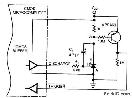
This circuit allows a microprocessor system to measure its own battery voltage. A Texas Instrument 71431 precision shunt regulator acts as a precision reference and integrator/amplifier, measuring its own supply via voltage-dependent charge/discharge time intervals. Notice that you must write a short control and voltage calculation software routine for your system. (View)
View full Circuit Diagram | Comments | Reading(652)
SCOPE_CALIBRATOR
Published:2009/7/20 4:05:00 Author:Jessie
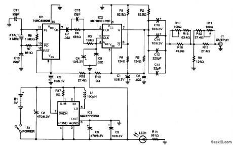
A 74HC4060 HCMOS oscillator/divider integrated circuit (IC1)was chosen for generating the master clock Choosing that part lets us use an inexpensive 4-MHz crystal The divide-by-16 output of IC1, at 250 kHz, is applied to a Motorola MC100EL32 divide-by-2 ECLips flip-flop (IC2) through level shift and decoupling components C7.015, and R6 Resistor R3 sets the input impedance seel1 by IC2 and divides the amplitude of IC1's output down to the ECLips input levels The MC100EL32 has transition times of both outputs specified at less than 350 ps (0.35 ns)and temperature-compensated output levels The divide-by-2 action of the device provides 125 kHz at approximately 800 mV p-p to the amplitude adjustment circuit and output stage. The output of IC2 is terminated with loads consisting of resistor pairs R1-R4 and R2-R5. The values shown provide an equivalent load voltage of about -2 V and a load impedance of 50 Ω. The output of IC2 is ac-coupled by capacitors C12, C13, C14, and C16 to an adjustable T-attenuator network. The various values of the coupling capacitors combine to transmit the fat rise-time edges (C12 and C13) while preventing droop at the 125-kHz base frequency (C14 and C16). (View)
View full Circuit Diagram | Comments | Reading(0)
ACCURATE_VOLTAGE_TO_FREQUENCY_CONVERTER
Published:2009/7/9 21:01:00 Author:May
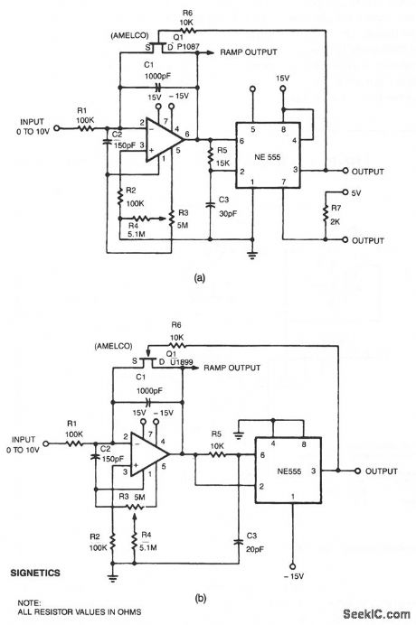
This linear voltage-to-frequency converter.a. achieves good linearity over 0 to -10 V. Its mirror image b. provides the same linearity over 0 to + 10 V, but it is not DTL/TTL compatible. (View)
View full Circuit Diagram | Comments | Reading(634)
CMOS_A_D_converter_with__10_volt_reference
Published:2009/7/20 4:04:00 Author:Jessie
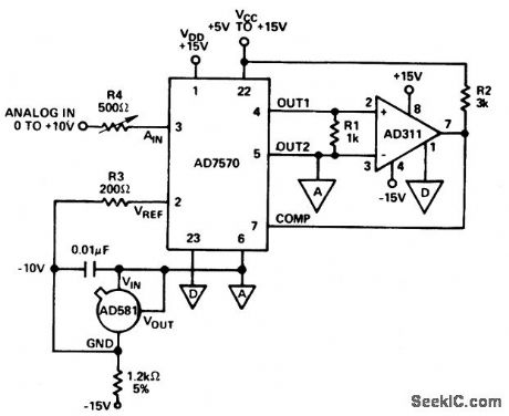
CMOS A/D converter with -10 volt reference (courtesy Analog Devices, Inc.). (View)
View full Circuit Diagram | Comments | Reading(897)
FLOW_METER
Published:2009/7/9 21:00:00 Author:May
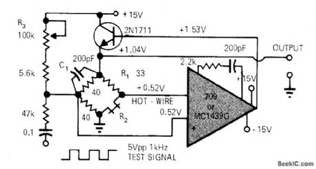
Simple opamp circuit with one transistor gives reliable hot-wire anemometer for measuring flow of gases or liquids. R2 is heated above ambient temperature in Wheatstone bridge including overheat resistor R1which is calibrated to be 30% larger than cold resistance of R2. Bridge is fed from power tran.sistor which is within feedback loop of opamp that senses bridge unbalance. Output of bridge is fed back to power transistor in correct phase for maintaining constant- temperature condition in which R2 is approximately equal to R1. Article covers construction of hot-wire probe made from Wollaston wire.-W. Bank, Build Your Own Constant-Temperature Hot-Wire Anemometer, EDN Magazine, Aug. 1, 1972, p 43. (View)
View full Circuit Diagram | Comments | Reading(4474)
52_watt_AF_power_amplifier_for_automotive_applications
Published:2009/7/20 4:04:00 Author:Jessie
52-watt AF power amplifier for automotive applications. Recommended supply voltage is 13.2 volts. No-signal current drain is typically 28 mA. Voltage gain is 51.5 dB (courtesy GTE Sylvania Incorporated). (View)
View full Circuit Diagram | Comments | Reading(494)
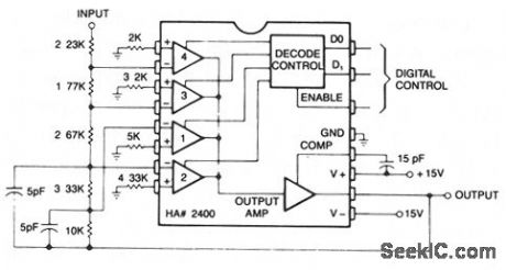
NONINVERTING_PROGRAMMABLE_GAIN_AMPLIFIER
Published:2009/7/9 21:00:00 Author:May
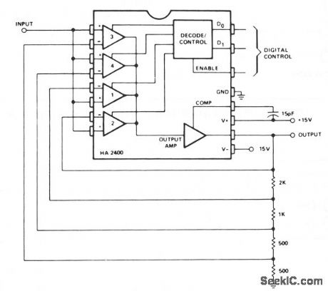
This is a noninverting amplifier configuration with feedback resistors chosen to produce a gain of 0, 1, 2, 4, or 8, depending on the digital control inputs. Comparators at the output could be used for automatic gain selection for auto-ranging meters, etc. (View)
View full Circuit Diagram | Comments | Reading(611)
8_bit_D_A_convertor_with_unipolar_output
Published:2009/7/20 4:03:00 Author:Jessie
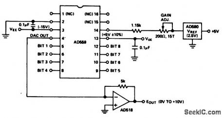
8-bit D/A convertor with unipolar output (courtesy Analog Devices, Inc.). (View)
View full Circuit Diagram | Comments | Reading(811)
INVERTING_PROGRAMMABLE_GAIN_AMPLIFIER
Published:2009/7/9 20:59:00 Author:May
This circuit can be programmed for a gain of 0, -1, -2, -4, or -8. This could also be accom-plished with one input resistor and one feedback resistor per channel in the conventional manner, but this would require eight resistors, rather than five. (View)
View full Circuit Diagram | Comments | Reading(543)
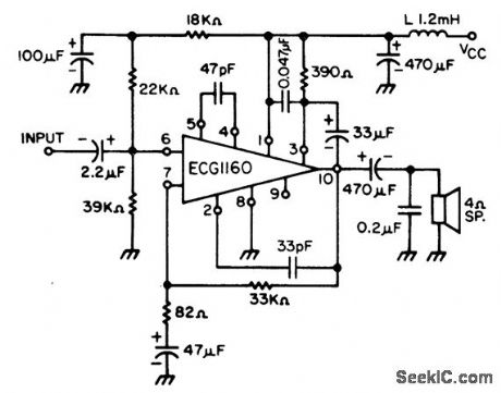
NAB_98_cm_s_equalizer_amplifier_for_car_stereo_using_an_ECG1087_module
Published:2009/7/20 4:03:00 Author:Jessie
NAB 9.8 cm/s equalizer amplifier for car stereo using an ECG1087 module. Typical voltage gain is 35 dB (courtesy GTE Sylvania Incorporated). (View)
View full Circuit Diagram | Comments | Reading(1022)
BATTERY_TEMPERATURE_SENSING_NICAD_CHARGER
Published:2009/7/9 20:58:00 Author:May
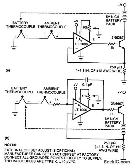
Two simple circuits permit Nicad charging of a battery based on temperature differences between the battery pack and the ambient temperature. This method has the advantage of allowing fast charging because the circuit senses the tempera-ture rise that occurs after charging is complete and the battery under charge is producing heat, not accumulating charge. (View)
View full Circuit Diagram | Comments | Reading(766)
10_bit_D_A_converter_with_precision_low_noise_reference
Published:2009/7/20 4:03:00 Author:Jessie
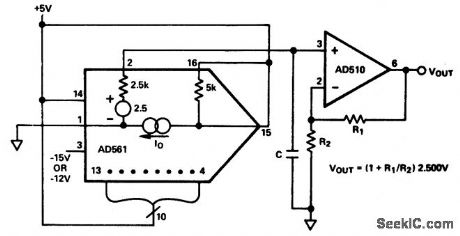
10-bit D/A converter with precision low-noise reference (courtesy Analog Devices, Inc.). (View)
View full Circuit Diagram | Comments | Reading(816)
12_bit_D_A_converter_with_precision_10_volt_reference
Published:2009/7/20 4:02:00 Author:Jessie
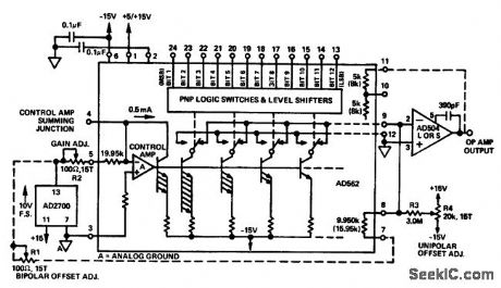
12-bit D/A converter with precision 10-volt reference (courtesy Analog Devices, Inc.). (View)
View full Circuit Diagram | Comments | Reading(818)
IR_REMOTE_EXTENDER
Published:2009/7/9 20:57:00 Author:May
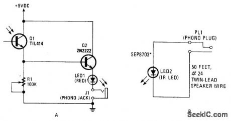
This circuit can be used to operate a VCR or CD player from another room. It's really an infrared signal repeaten The signal from the remote is received and then retransmitted over wires to an infrared LED. The beam from the LED is then picked up by the receiving window on the VCR or CD player.
The visible light LED (LED1) in series with the IR unit (LED2) is used to indicate that the transmit-ted signal has been detected. The 100-kΩ trimmer potentiometer (R1) adjusts the repeater's sensitiity.The resistor that is usually found in series with the LEDs is omitted, because the voltage reading is about 1.0 Vdc as a result of the voltage drop across the lines. (View)
View full Circuit Diagram | Comments | Reading(911)
Precision_12_bit_D_A_converter
Published:2009/7/20 4:01:00 Author:Jessie
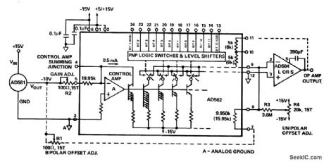
Precision 12-bit D/A-converter (courtesy Analog Devices, Inc.). (View)
View full Circuit Diagram | Comments | Reading(0)
RF_PROBE_1
Published:2009/7/9 20:57:00 Author:May
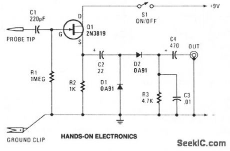
Transistor Q1-conftgured as a source-follower buffer stage, offering a bit under unity voltage gain-gives the unit a high-impedance input of about 1 MΩ shunted by about 10 pF, which keeps only minimal loading on the equipment being tested. C1 serves as input dc blocking capacitor. The Q1 output is coupled by C2 to a simple AM detector circuit made up of D1, D2, R3 and C3. Capacitor C4 provides output dc blocking. Total current consumption should be somewhere around 1 mA. The circuit responds to frequencies from 100 kHz to well over 50 MHz. (View)
View full Circuit Diagram | Comments | Reading(1029)
DIGITAL_PHASE_METER
Published:2009/7/20 4:00:00 Author:Jessie
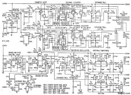
Measures phase angle between satellite signal and reference pulse. Bistable switch operates as gate that connects 500-cps pulse train to 3-decade decimal counter during time between reference and signal pulses. Two channels measure phase angles of north-south and east-west fine signals.-C. A. Schroeder, C. H. Looney, Jr., and H. E. Carpenter, Jr., Tracking Orbits of Man-made Moons, Electronics, 32:1, p 33-37. (View)
View full Circuit Diagram | Comments | Reading(1145)
Voltage_to_frequency_converter_for_bipolar_operation
Published:2009/7/20 3:58:00 Author:Jessie
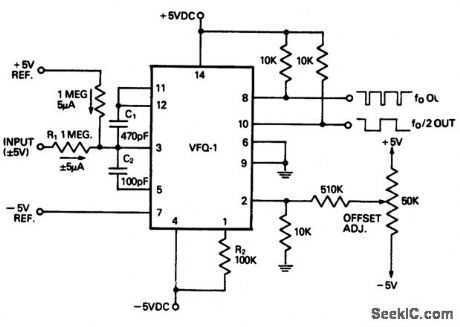
Voltage-to-frequency converter for bipolar operation. Full scale output is 20 kHz.Chip used is the Datel VFQ-1 14-pin DIP.outputs at fo and fo/2 are possible(courtesy Datel Systems, Inc.). (View)
View full Circuit Diagram | Comments | Reading(872)
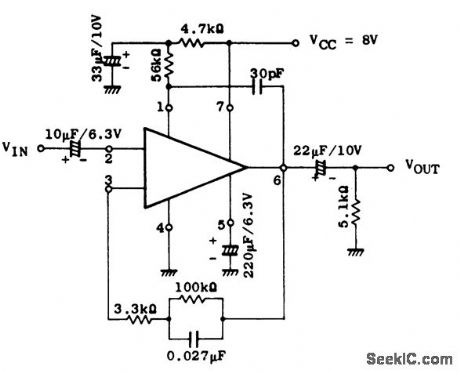
21_watt_AF_power_amplifier_for_radio
Published:2009/7/20 3:57:00 Author:Jessie
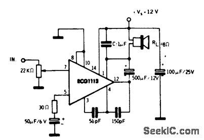
2.1-watt AF power amplifier for radio. The 2.1-watt rating is for an 8-ohm load. The ECG1113 is a 14-pin QIP. Recommended supply voltage is 12 volts, which makes it ideal for automotive applications. Current drain at maximum output is 235 mA. Typical voltage gain is 70 dB (courtesy GTE Sylvania Incorporated). (View)
View full Circuit Diagram | Comments | Reading(613)
| Pages:881/2234 At 20881882883884885886887888889890891892893894895896897898899900Under 20 |
Circuit Categories
power supply circuit
Amplifier Circuit
Basic Circuit
LED and Light Circuit
Sensor Circuit
Signal Processing
Electrical Equipment Circuit
Control Circuit
Remote Control Circuit
A/D-D/A Converter Circuit
Audio Circuit
Measuring and Test Circuit
Communication Circuit
Computer-Related Circuit
555 Circuit
Automotive Circuit
Repairing Circuit