
Circuit Diagram
Index 892
20000_V_INDUCTIVE_STORAGE_SUPPLY
Published:2009/7/20 5:55:00 Author:Jessie

Consists of shunt-regulated electronically switched inductive energy storage system in which coil L1 is charged through vacuum switch. When high voltage is needed, V2 is fired to deionize V1. Cathode capacitor of V2 is then charged to 20,000 V by coil current, at which time electronic feedback regulator in shunt with L1 draws current to maintain constant output voltage.-R. L. Gamblin, Ohmic Heating Circuits for Plasma Physics, Electronics, 32:41, p 57-59. (View)
View full Circuit Diagram | Comments | Reading(628)
Acoustic_thermometer
Published:2009/7/20 5:54:00 Author:Jessie

Acoustic thermometer. This circuit relies on the principle that the speed of sound varies predictably with temperature in a known medium. The sensor used is in effect a thermally dependent delay line. A40 kHz clock is used to drive a transmitting transducer (courtesy Analog Devices, Inc.). (View)
View full Circuit Diagram | Comments | Reading(2020)
Electronic_thermometer_for_all_temperature_scales
Published:2009/7/20 6:12:00 Author:Jessie

Electronic thermometer for all temperature scales (courtesy Analog Devices, Inc.). (View)
View full Circuit Diagram | Comments | Reading(894)
8_channel_temperature_multiplexer
Published:2009/7/20 6:12:00 Author:Jessie
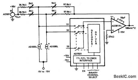
8-channel temperature multiplexer. An additional six temperature transducers should be added; only two are shown (courtesy Analog Devices, Inc.). (View)
View full Circuit Diagram | Comments | Reading(946)
Temperature_differential_measurement_circuit
Published:2009/7/20 6:10:00 Author:Jessie
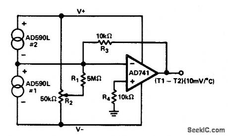
Temperature differential measurement circuit (courtesy Analog Devices, Inc.). (View)
View full Circuit Diagram | Comments | Reading(1013)
Precision_temperature_regulator_for_regulating_temperature_of_ovens_hot_plates_fluids_air_and_gases
Published:2009/7/20 6:09:00 Author:Jessie

Precision temperature regulator for regulating temperature of ovens, hot plates, fluids, air and gases. It can control up to 600 watts and has adjustable gain and temperature with built-in protection against transient voltages (courtesy General Electric Company). (View)
View full Circuit Diagram | Comments | Reading(1936)
Thermistor_thermometer_that_can_be_calibrated_for_two_temperature_ranges
Published:2009/7/20 6:08:00 Author:Jessie

Thermistor thermometer that can be calibrated for two temperature ranges. If another meter is used in place of the one specified (1500 ohms) the resistance of M plus R5 should equal 5350 ohms. To calibrate for the 32°F to 122°F scale immerse R3 in crushed ice and adjust R4 for zero current; mark the location of R4's knob pointer. Replace R3 with the low-resistance test resistor supplied, and adjust R7 for full-scale deflection; mark R7's position. Save the low-resistance test resistor. This completes the 32°F to 122°F calibration. To calibrate for -40°F to +32°F replace R3 with the high-resistance test resistor supplied, and adjust R4 for zero current; mark R4's location. Replace the rest resistor with R3. Immerse R3 in crushed ice, and adjust R7 for full-scale deflection; mark R7's location. This completes the -40° to +32°F calibration (courtesy General Electric Company).
(View)
View full Circuit Diagram | Comments | Reading(1564)
PREFERRED_300_V_D_C_REGULATOR
Published:2009/7/20 6:06:00 Author:Jessie

Provides either polarity of output with 1% regulation, from minimum of 350 v d-c input. Maximum output current is 125 ma for single series tube section and 100 ma per triode section when two or morn are paralleled. Minimum value of C5 is 4 mfd.-NBS, Hand-book Preferred Circuits Navy Aeronautical Electronic Equipment, Vol. 1, Electron Tube Circuits, 1963, PC 3, p 3-2. (View)
View full Circuit Diagram | Comments | Reading(901)
Negative_voltage_regulator_using_an_ECG923_or_ECG923D_precision_regulator_IC
Published:2009/7/20 6:06:00 Author:Jessie

Negative voltage regulator (15 volts) using an ECG923 or ECG923D precision regulator IC. For metal can applications, where Vz is required, an external 6.2-volt zener should be connected in series with the regulated output. R1 is 3.65 ohms and R2 is 11.5 ohms for a ±5% fixed output (courtesy GTE Sylvania Incorporated). (View)
View full Circuit Diagram | Comments | Reading(759)
Short_circuit_protected_current_boost_regulator_using_the_ECG9XX_series_of_regulators
Published:2009/7/20 6:05:00 Author:Jessie

Short-circuit protected current boost regulator using the ECG9XX series of regulators.The ratings of the ECG9XX series are as follows: ECG960, 5 volts; ECG962, 6 volts; ECG966, 12 volts; ECG968, 15 volts; and ECG972, 24 volts. The current-sensing ECG2:8 transistor must be able to handle the current of the three-terminal regulator; therefore, a 4-ampere transistor is specified. Resistor R in conjunction with the VBE of the pass transistor determines when the transistor begins to conduct. Input-output differential voltage minimum is increased by the VBE of the pass transistor (courtesy GTE Sylvania Incorporated). (View)
View full Circuit Diagram | Comments | Reading(1201)
BLOCKING_OSCILLATOR_SWITCHING_VOLT_AGE_REGULATOR
Published:2009/7/20 6:05:00 Author:Jessie

Efficiency is improved greatly by having current of 2N379l transistor flow through load. Differential-amplifier voltage-sensing arrangement controls ac lion of oscillator to maintain constant output voltage. Will regulate 24.v output lo within 1% over load range of 100 ma to 2 amp. Oscillator frequency is 6 kc.-H. Weber, Two Unique Switching Voltage Regulators Using Blocking Oscillators, Motorola Application Note AN-163, Aug. 1965. (View)
View full Circuit Diagram | Comments | Reading(678)
6_channel_scanning_digital_thermometer_with_printer_output_
Published:2009/7/20 6:04:00 Author:Jessie
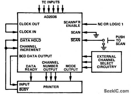
6-channel scanning digital thermometer with printer output (courtesy Analog Devices, Inc.) (View)
View full Circuit Diagram | Comments | Reading(938)
Current_regulator_using_the_ECG9XX_series_of_fixed_voltage_regulators
Published:2009/7/20 6:04:00 Author:Jessie

Current regulator using the ECG9XX series of fixed voltage regulators. The series and ratings are as follows: ECG960, 5.0 volts; ECG962, 6.0 volts; ECG966, 12 volts: ECG968, 15volts; and ECG972, 24 volts. It is recommended that the regulator input be bypassed if the regulator is at a distance from the power supply filters. A 0.33 μF or larger tantalum or Mylar should be used. If an aluminum type is used it should be 1.0 pF or larger. Using the 5-volt ECG960 as an example, resistor R determines the current as follows: Io = (5 volts/R) + IQ, where IQ is 1.5 mA over line and load changes (courtesy GTE Sylvania Incorporated). (View)
View full Circuit Diagram | Comments | Reading(565)
Matrix_temperature_multiplexer_
Published:2009/7/20 6:04:00 Author:Jessie

Matrix temperature multiplexer (courtesy Analog Devices, Inc.) (View)
View full Circuit Diagram | Comments | Reading(1971)
SIMPLE_5_VOLTAGE_SUPPLY
Published:2009/7/20 5:53:00 Author:Jessie

Provides -6 v and both positive and negative 12 and 18 v outputs, each regulated by zeners, for linear integrated-circuit tester and for integrated circuits under lest. Transformer has cenfertapped 24-v secondary. Lamp across half of secondary operates at 12 v to extend life.-J. N. Giles, How to Measure Linear-IC Performance, EEE, 14:8, p 62-68 and 161. (View)
View full Circuit Diagram | Comments | Reading(555)
HOLD_SAMPLE_HOLD_PHASE_DETECTOR
Published:2009/7/20 5:53:00 Author:Jessie

Has two mos transistors as series switches and a third as impedance transformer. C5, C6, and C8 are charged to voltages proportional to phase difference between programmed dilvider's output and reference signal. Voltages are summed with pretuning voltage to control vco of frequency synthesizer for military uhf transceiver.-L. F. Blachowicz, Dial any Channel to 500 Mhz, Electronics, 39:9, p 60-69. (View)
View full Circuit Diagram | Comments | Reading(830)
REFERENCE_AMPLIFIER_12_V_REGULATED_SUPPLY
Published:2009/7/20 5:52:00 Author:Jessie

Uses integrated device consisting of zener diode and npn transistor in single pellet, to serve dual function of voltage reference element and error voltage amplifier. Provides up to 100 ma. 180-ohm series resistor provides short-circuit protection by limiting output current to less than 200 ma. Output regulation is better than 0.3% for line voltage variations of 10%.- Trcmsistor Manual, Seventh Edition, General Electric Co., 1964, p 231. (View)
View full Circuit Diagram | Comments | Reading(556)
Temperature_operated_relay_for_soldering_iron_furnace_etc
Published:2009/7/20 5:52:00 Author:Jessie

Temperature-operated relay for soldering iron, furnace, etc. This circuit will control the temperature at thermistor R1 within 1°over the temperature range of 20°F to t 50°F. For other temperature ranges change R1; it should have about 1000 ohms resistance in the center of the desired control range. Pl can be substituted with other types of sensing devices (e.g., photo resistor). By using K1 to operate a large contactor heavier loads can be controlled. As is, K1 is rated for 5 amperes (courtesy General Electric Company). (View)
View full Circuit Diagram | Comments | Reading(1969)
Tracking_positive_and_negative_voltage_reference_using_an_ECG947_dual_operational_amplifier
Published:2009/7/20 5:51:00 Author:Jessie

Tracking positive and negative voltage reference using an ECG947 dual operational amplifier. The ECG947 is short-circuit protected and requires no external components for frequency compensation (courtesy GTE Sylvania Incorporated). (View)
View full Circuit Diagram | Comments | Reading(609)
LAMP_DIMMER
Published:2009/7/20 5:50:00 Author:Jessie

Silicon symmetrical switches Q1 and Q2 control phase angle at which current flows fhrough 600-w fluorescent or incandescent lamp load. Q1 handles load current while Q2 serves as symmetrical relaxation oscillator, with setting of R1 determining point in each half-cycle at which Q2 fires. Since system is symmetrical, it cannot be damaged by transients or line surges.-S. B. Gray, Home and Auto Controls, Electronics, 36:19, p 52-56. (View)
View full Circuit Diagram | Comments | Reading(0)
| Pages:892/2234 At 20881882883884885886887888889890891892893894895896897898899900Under 20 |
Circuit Categories
power supply circuit
Amplifier Circuit
Basic Circuit
LED and Light Circuit
Sensor Circuit
Signal Processing
Electrical Equipment Circuit
Control Circuit
Remote Control Circuit
A/D-D/A Converter Circuit
Audio Circuit
Measuring and Test Circuit
Communication Circuit
Computer-Related Circuit
555 Circuit
Automotive Circuit
Repairing Circuit