
Circuit Diagram
Index 891
LIGHTS_ON_WARNING
Published:2009/7/9 4:57:00 Author:May

Because power for the circuit is obtained from the car's side lights, the circuit can't oscillate unless the lights are on. The reset pin on the 555 connects to transistor Q1. The base of Q1 is connected through R1 to the ignition auxiliary terminal on the car's fuse box. When the ignition is turned on, power is sup-plied to the base of Q1, which turns it on. With Q1 turned on, pin 4 of U1 is tied low, which disables the oscillator and inhibits the alarm. If the ignition is tumed off while the lights are on, power is applied to the 555 and Q1 is turned off, and the alarm starts. Switch S1 is an optional override. (View)
View full Circuit Diagram | Comments | Reading(751)
THIRD_BRAKE_LIGHT
Published:2009/7/9 4:56:00 Author:May

The circuit is designed to light (via SCR1 and SCR2) only when both the left and right brake lights are activated. The circuit operates on 12-V negative-ground systems. When the brake pedal is depressed, 12 V is applied to the left and right brake lights. The gates of the two SCRs are trig-gered and current flows through the SCRs, which turns on the third brake light. (View)
View full Circuit Diagram | Comments | Reading(843)
GROUND_FAULT_HALL_SENSOR
Published:2009/7/9 4:54:00 Author:May

No electrical contact exists between the circuit and the conductor. The 7474 flip-flop is triggered by the output from the Hall sensor, op amp, and Schmitt trigger. This triggering activates the optocoupler, turns on the triac, and trips the circuit breaker. (View)
View full Circuit Diagram | Comments | Reading(2287)
INTERIOR_CONVENIENCE_LIGHT
Published:2009/7/9 4:53:00 Author:May

When the door is closed, this circuit keeps the dome light on for a period determined by R1/C1. The time is approximately (1.1)R1 x C1. (View)
View full Circuit Diagram | Comments | Reading(764)
SELF-OSCILLATING_FLYBACK-SWITCHING_CONVERTER
Published:2009/7/9 4:52:00 Author:May

Regulation is provided by taking the rectified output of the sense winding and applying it as a bias to the base of Q2 via zener D1. The collector of Q2 then removes drive from the gate of Q1. Therefore, if the output voltage should increase, Q2 removes the drive to Q1 earlier, shortening the on time, and the output voltage will remain the same. Dc outputs are obtained by merely rectifying and filtering secondary windings, as done by D5 and C4. (View)
View full Circuit Diagram | Comments | Reading(1737)
DIGITAL_pH_METER
Published:2009/7/9 4:52:00 Author:May

3130 CMOS opamp gives required high input impedance for pH probe at low cost. Output of probe, ranging from positive generated DC voltage for low pH to 0 V for pH 7 and negative voltages for high pH values, is amplified in circuit that provides gain adjustment to correct for temperature of solution being measured. For analog reading, output of opamp can be fed directly to center-scale milliammeter through 100K calibrating pot. For digital display giving reading of 7.00 for 0-V output, pH output is converted to calibrated current for summing with stable offset current equal to 700 counts. This is fed to current-to-frequency converter driving suitable digital display. Standard pH buffer solutions are used for calibration.-D. Lancaster, CMOS Cookbook, Howard W. Sams, Indianapolis, IN, 1977, p 347-349. (View)
View full Circuit Diagram | Comments | Reading(2882)
Four_channel_sequencing_multiplexer
Published:2009/7/20 6:21:00 Author:Jessie

Four-channel sequencing multiplexer. The analog switch package is an Intersil IH5052 16-pin CMOS DIP (courtesy Intersil, Inc.). (View)
View full Circuit Diagram | Comments | Reading(716)
2_level_16_channel_multiplexer
Published:2009/7/20 6:20:00 Author:Jessie

2-level 16-channel multiplexer (courtesy Motorola Semiconductor Products Inc.). (View)
View full Circuit Diagram | Comments | Reading(587)
SNAP_ACTION_A_C_PHASE_CONTROL
Published:2009/7/20 6:20:00 Author:Jessie

Provides snap-action switching of load in response to change in d-c signal, a-c signal, or variable resistance element, using small differentiating network R1-R2-C1 that peaks leading edge of pedestal. Triggering can occur only near beginning of each half-cycle, to give snap-on and snap-off action.- Silicon Controlled Rectifier Manual, Third Edition, General Electric Co., 1964, p 135. (View)
View full Circuit Diagram | Comments | Reading(504)
DIAC_TRIAC_PHASE_CONTROL_OF_5_AMP_LOAD
Published:2009/7/20 6:19:00 Author:Jessie

Uses two types of semiconductor switches together with R and C to give continuous control of power. Addition of second phase shift network (enclosed in dashed box) extends range of control to cover 5 to 95% of full power.-M. P. Southworth, Bidirectional Static Switch Simplifies Ac Control, Control Engineering, March 1964, p 75-76. (View)
View full Circuit Diagram | Comments | Reading(828)
2_input_analog_multiplexer_using_an_MC14007_dual_pair_plus_inverter
Published:2009/7/20 6:18:00 Author:Jessie

2-input analog multiplexer using an MC14007 dual pair plus inverter (courtesy Motorola Semiconductor Products Inc.). (View)
View full Circuit Diagram | Comments | Reading(568)
8_cannel_analog_multiplexer_with_two_methods_of_selection
Published:2009/7/20 6:17:00 Author:Jessie

8-cannel analog multiplexer with two methods of selection. Two MC14016s as shown in (a) can be connected for an 8-channel multiplexer. The MC14022 octal counter in (b) is used for time division multiplexing (stepping switch) and each channel is on for one period of the scanning clock. The MC14028 decoder is used for control in applications requiring selection with a 3-bit binary code (courtesy Motorola Semiconductor Products Inc.). (View)
View full Circuit Diagram | Comments | Reading(1572)
The boiler electric cleaner
Published:2011/7/22 5:31:00 Author:qqtang | Keyword: electric cleaner

The boiler electric cleaner of the example is to process the water with high frequency electric field, so the physical characters of the minerals in the water are changed, so the dirt is removed or avoided. The working principle of the circuitThe boiler electric cleaner circuit consists of the power supply circuit, 200khz rectangular wave oscillator, drive amplifier circuit and output indicating circuit and so on, see as figure 8-153.
The power supply circuit consists of the transformer TV, rectifier diode VD4-VD9, filter capacitors of C5 and C6, etc. (View)
View full Circuit Diagram | Comments | Reading(564)
Positive_voltage_regulator_5_volts_with_foldback_current_limiting_using_an_ECG915_or_ECG915D
Published:2009/7/20 6:03:00 Author:Jessie

Positive voltage regulator (5 volts) with foldback current limiting using an ECG915 or ECG915D.For a ±5% fixed output R1 is 2.15 ohms and R2 is 4.99 ohms(courtesy GTE Sylvania Incorporated). (View)
View full Circuit Diagram | Comments | Reading(622)
0_10_V_TWO_ZENER
Published:2009/7/20 6:02:00 Author:Jessie

Simple arrangement provides source of well-regulated adjustable voltage. First zener diode tends to act as pre-regulator, improving dynamic regulation.- Zener Diode Handbook, International Rectifier Corp., 1960, p 54. (View)
View full Circuit Diagram | Comments | Reading(558)
Simple_weighing_system_with_199_pound_15_ounce_maximum_ADC1105_
Published:2009/7/20 6:01:00 Author:Jessie
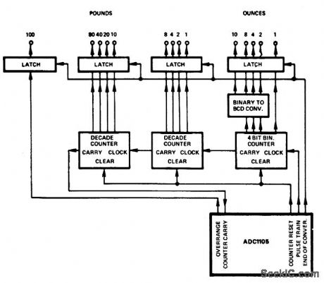
Simple weighing system with 199-pound 15-ounce maximum ADC1105 (courtesy Analog Devices, Inc). (View)
View full Circuit Diagram | Comments | Reading(841)
Positive_precision_voltage_regulator_15_volts_using_an_ECG915_or_ECG915D_IC
Published:2009/7/20 6:01:00 Author:Jessie

Positive precision voltage regulator (15 volts) using an ECG915 or ECG915D IC.R1 is 7.87 ohms, R2 is 7.15 ohms and Rsc is 10 ohms for a ±5% fixed output (courtesy GTE Sylvania Incorporated). (View)
View full Circuit Diagram | Comments | Reading(505)
Water_seepage_alarm_using_an_LM3909_chip
Published:2009/7/20 6:00:00 Author:Jessie

Water seepage alarm using an LM3909 chip. Circuitry inside dashed lines is the LM3909. Standby battery current drain is 100μA. The multivibrator rate is about 1 hertz when it starts and increases as more moisture passes across the sensor. The sensor should be part of the box housing the circuitry. The sensor consists of two 6-inch strips of metal about an eighth-inch apart. Stainless steel or copper will work well. Battery life for a single alkaline penlight cell is about 3 months (courtesy National Semiconductor Corporation.) (View)
View full Circuit Diagram | Comments | Reading(989)
Programmable_mass_spectrometer_voltage_source_
Published:2009/7/20 5:58:00 Author:Jessie
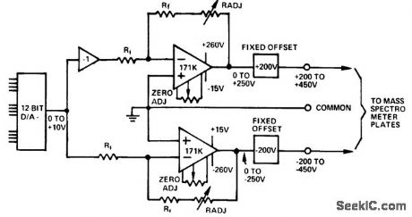
Programmable mass spectrometer voltage source (courtesy Analog Devices, Inc.). (View)
View full Circuit Diagram | Comments | Reading(905)
Thermistor_operated_temperature_alarm_that_can_ring_a_bell_turn_on_a_light_or_ring_a_buzzer_Any_temperature_between_115°_and_165°F_can_be_detected
Published:2009/7/20 5:57:00 Author:Jessie

Thermistor-operated temperature alarm that can ring a bell, turn on a light or ring a buzzer. Any temperature between 115° and 165°F can be detected. To calibrate adjust the following spacings of the magnet from the coil for the indicated temperatures: 1.5 inches for 117°F, t inch for 129°F, 0.75 inch for 138°F, 0.625 inch for 149°F and 0.5 inch for 164°F. Then immerse R1 in the medium heated to the desired point to sound the alarm. Turn on 51 and adjust the bias magnet to sound the alarm. Secure the magnet (courtesy General Electric Company). (View)
View full Circuit Diagram | Comments | Reading(905)
| Pages:891/2234 At 20881882883884885886887888889890891892893894895896897898899900Under 20 |
Circuit Categories
power supply circuit
Amplifier Circuit
Basic Circuit
LED and Light Circuit
Sensor Circuit
Signal Processing
Electrical Equipment Circuit
Control Circuit
Remote Control Circuit
A/D-D/A Converter Circuit
Audio Circuit
Measuring and Test Circuit
Communication Circuit
Computer-Related Circuit
555 Circuit
Automotive Circuit
Repairing Circuit