
Circuit Diagram
Index 893
The 3-phase AC constant phase sequence controller
Published:2011/7/22 5:39:00 Author:qqtang | Keyword: phase sequence controller, 3-phase

The working principle of the circuitThe working principle of the circuit consists of the the power supply circuit, phase sequence detecting circuit and control circuit, see as figure 8-152.
The power supply circuit consists of the transformer T, rectifier bridge pile UR, resistor R4, regulated diode VS4 and filter capacitor C.The phase sequence detecting circuit consists of the rectifier diode VD1-VD3, current limit resistor R1-R3, regulated diode VS1-VS3 and D1-D3 in IC1 of the NOR gate Schmidt trigger integrated circuit. (View)
View full Circuit Diagram | Comments | Reading(2364)
Positive_precision_voltage_regulator_using_an_ECG915_or_ECG915D_IC
Published:2009/7/20 5:50:00 Author:Jessie

Positive precision voltage regulator (5 volts) using an ECG915 or ECG915D IC. For a ±5% fixed output R1 is 2.15 ohms, R2 is 4.99 ohms and Rsc is 10 ohms (courtesy GTE Sylvania Incorporated). (View)
View full Circuit Diagram | Comments | Reading(533)
_Current_boost_regulator_for_5_amperes_using_the_ECG9XX_series_of_
Published:2009/7/20 5:49:00 Author:Jessie

Current boost regulator for 5 amperes using the ECG9XX series of regulators. The ratings of the ECG9XX series are as follows:ECG960,5 volts;ECG962,6 volts;ECG966,12 volts;ECG968,15 volts; and ECG972,24 volts. Resistor determines when the transistor begins to conduct. This circuit is not short-circuit proof. Input-output differential voltage minimum is increased by the VBE of the transistor (courtesy GTE Sylvania Incorporated). (View)
View full Circuit Diagram | Comments | Reading(955)
Light_intensity_absorbance_circuit_using_the_757N_log_ratio_module_and_the_AD2009_3_1_2_digit_DPM
Published:2009/7/20 5:49:00 Author:Jessie

Light intensity absorbance circuit using the 757N log ratio module and the AD2009 3 1/2-digit DPM (courtesy Analog Devices, Inc.). (View)
View full Circuit Diagram | Comments | Reading(935)
MEASURING_PHASE_UP_TO_2000_MC
Published:2009/7/20 5:47:00 Author:Jessie

Output is fed to cro having 100-kc bandwidth. In operation, time delay of both channels is equalized by applying identical signal to both inputs, then reference and unknown signals are applied to input terminals and variable delay line is adjusted again for null on chopper amplifier that drives d-c milliammeter.-Y. P. Yu, How to Measure Phase at High Frequencies, Electronics, 34:11, p 54-56. (View)
View full Circuit Diagram | Comments | Reading(567)
Phasemeter_for_sinusoidal_signals
Published:2009/7/20 5:47:00 Author:Jessie

Phasemeter for sinusoidal signals. This circuit provides a good linear measure of phase for small angles up to 14° and a sinusoidal measure of angles between +90°and -90°(courtesy Analog Devices, Inc.). (View)
View full Circuit Diagram | Comments | Reading(942)
Electronic_thermostat
Published:2009/7/20 5:45:00 Author:Jessie

Electronic thermostat (courtesy Analog Devices, Inc.). (View)
View full Circuit Diagram | Comments | Reading(0)
12_volt_power_supply_using_an_over_winding_from_a_phonograph_motor
Published:2009/7/20 5:32:00 Author:Jessie
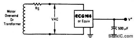
12-volt power supply using an over winding from a phonograph motor. With 16 volts AC the output is approximately 12 volts DC. Rs is the series resistance of the winding (courtesy GTE Sylvania Incorporated). (View)
View full Circuit Diagram | Comments | Reading(614)
Voltage_boosted_40_volt_100_mA_regulator_with_short_circuit_current_limiting_
Published:2009/7/20 5:32:00 Author:Jessie
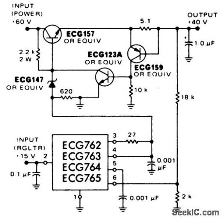
Voltage-boosted 40-volt 100 mA regulator with short-circuit current limiting (courtesy GTE Sylvania Incorporated). (View)
View full Circuit Diagram | Comments | Reading(569)
The car electric igniter (2)
Published:2011/7/21 21:19:00 Author:qqtang | Keyword: electric igniter
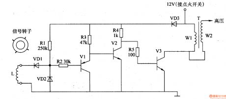
Here is to introduce the car electric igniter which is a contactless transistor igniter, the circuit is simple and easy to make.The principle of the circuitThe car electric igniter circuit consists of the pulse signal generator and switch booster circuit, see as figure 7-133.
The synchronous pulse signal generator circuit consists of the signal rotor (permanent magnet), electromagnet coil L and diode VD1 and VD2.The switch booster circuit consists of the transistor V1-V3, resistor R1-R5 and booster transformer T. (View)
View full Circuit Diagram | Comments | Reading(3410)
45_watt_AF_power_amplifier_for_a_4_ohm_load
Published:2009/7/20 5:31:00 Author:Jessie
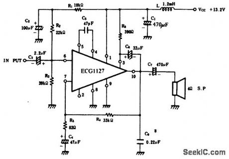
4.5-watt AF power amplifier for a 4-ohm load. Recommended supply voltage is 13.2 volts, which makes this circuit ideal for automotive applications. Typical voltage gain is 50 dB (courtesy GTE Sylvania Incorporated). (View)
View full Circuit Diagram | Comments | Reading(804)
15_volt_1_ampere_regulator_with_short_circuit_protection
Published:2009/7/20 5:30:00 Author:Jessie
15-volt 1-ampere regulator with short-circuit protection (courtesy GTE Sylvania Incorporated). (View)
View full Circuit Diagram | Comments | Reading(499)
4_watt_OTL_power_amplifier_using_10_pin_TO3
Published:2009/7/20 5:30:00 Author:Jessie
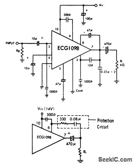
4-watt OTL power amplifier using 10-pin TO3. Typical supply voltage is 14 volts. The circuit is designed for a 4-ohm load and its efficiency is 60%. Typical voltage gain is 39 dB. Input impedance is 6.5K. Bandwidth is 70 hertz to 20 kilohertz. Although the ECG1098 can handle short-circuit conditions for short durations, it is recommended that the protection circuit shown be used if long periods with the speaker load shorted occur (courtesy GTE Sylvania Incorporated). (View)
View full Circuit Diagram | Comments | Reading(891)
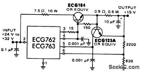
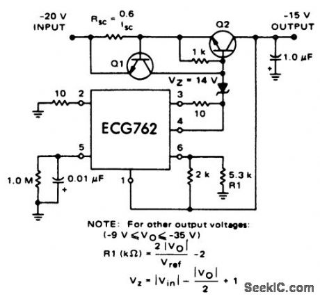
15_volt_regulator
Published:2009/7/20 5:30:00 Author:Jessie
15-volt regulator. Input voltage for ECG762 and ECG763 should not exceed 38 volts and for the ECG764 and ECG765 should not exceed 22 volts (courtesy GTE Sylvania Incorporated). (View)
View full Circuit Diagram | Comments | Reading(585)
5_volt_5_ampere_regulator_with_remote_sensing_PNP_current_boost
Published:2009/7/20 5:29:00 Author:Jessie
5-volt 5-ampere regulator with remote sensing PNP current boost (courtesy GTE Sylvania Incorporated). (View)
View full Circuit Diagram | Comments | Reading(617)
15_volt_regulator_with_current_limit
Published:2009/7/20 5:27:00 Author:Jessie
15-volt regulator with current limit (courtesy GTE Sylvania Incorporated). (View)
View full Circuit Diagram | Comments | Reading(581)
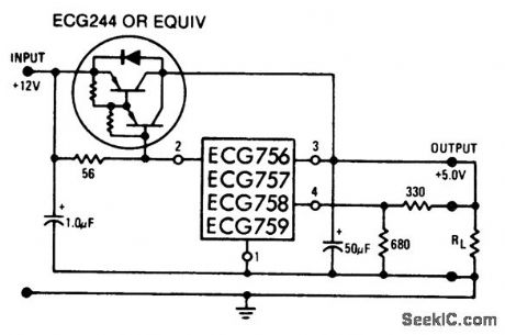
5_volt_regulator
Published:2009/7/20 5:27:00 Author:Jessie
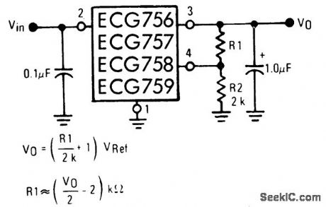
5-volt regulator. Input voltage should not exceed 22 volts for the ECG758 and ECG759 or 38 volts for the ECG756 and ECG757. All of these units are 4-lead packages (courtesy GTE Sylvania Incorporated). (View)
View full Circuit Diagram | Comments | Reading(496)
The industrial X ray defect detector time delay control switch
Published:2011/7/22 5:46:00 Author:qqtang | Keyword: X ray, defect detector, time delay

The working principle of the circuit The industrial X ray defect detector time delay control switch circuit consists of the regulated filter circuit, time delay control circuit A, delay control circuit B and control executing circuit, see as figure 8-150.
The regulated filter circuit consists of the capacitors of C5 and C6 and the 3-phase regulated integrated circuit IC3. The time delay control circuit A consists of the resistor R1-R3, capacitors of C1 and C2, time-based integrated circuit IC1, diode VD1, relay K1, LED diode VL1 and control key S1. (View)
View full Circuit Diagram | Comments | Reading(1371)
D_A_convener_with_fast_bipolar_output_using_the_Datel_DAC_IC_10BC_and_AM_452
Published:2009/7/20 5:26:00 Author:Jessie

D/A convener with fast bipolar output using the Datel DAC-IC 10BC and AM-452.See coding table(courtesy Datel Systems, Inc.). (View)
View full Circuit Diagram | Comments | Reading(972)
D_A_convertner_in_bipolar_operation
Published:2009/7/20 5:25:00 Author:Jessie

D/A convertner in bipolar operation (courtesy Analog Devices, Inc.). (View)
View full Circuit Diagram | Comments | Reading(802)
| Pages:893/2234 At 20881882883884885886887888889890891892893894895896897898899900Under 20 |
Circuit Categories
power supply circuit
Amplifier Circuit
Basic Circuit
LED and Light Circuit
Sensor Circuit
Signal Processing
Electrical Equipment Circuit
Control Circuit
Remote Control Circuit
A/D-D/A Converter Circuit
Audio Circuit
Measuring and Test Circuit
Communication Circuit
Computer-Related Circuit
555 Circuit
Automotive Circuit
Repairing Circuit