
Circuit Diagram
Index 861
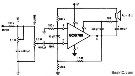
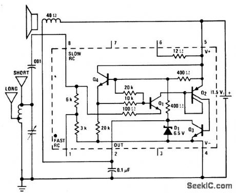
025_watt_AF_amplifier_using_a_16_ohm_speaker
Published:2009/7/20 2:22:00 Author:Jessie
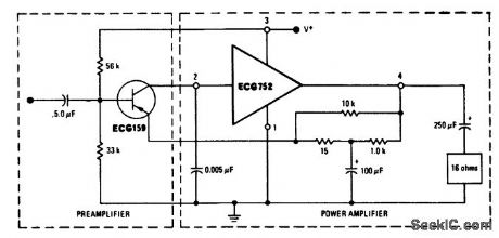
0.25-watt AF amplifier using a 16-ohm speaker. Supply voltage should be approximately 12 volts (courtesy GTE Sylvania Incorporated). (View)
View full Circuit Diagram | Comments | Reading(520)
6_VARISTOR_PHASE_SHIFT_VTO
Published:2009/7/20 2:22:00 Author:Jessie
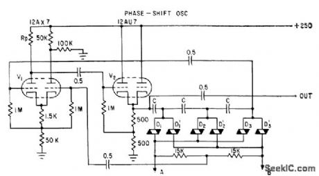
Range is ten times lowest frequency, with upper limit of several kc, depending on values of C. Triode differential amplifier V1 is first stage of oscillator. One input grid, for a-c amplification, goes to output of phase-shift circuit. Other grid goes to centertap across SiC varistors. -M. Uno, Varistor Network Controls Voltage-Tuned Oscillator, Electronics, 34:30, p 44-47. (View)
View full Circuit Diagram | Comments | Reading(547)
TIME_OUT_WARNING_1
Published:2009/7/20 2:22:00 Author:Jessie
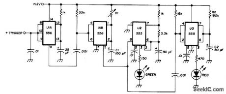
Transceiver-actuated circuit inhibits FM repeater timer override. Uses 556 dual timer and two 555 timers. Triggers on positive step-input voltage from transceiver when PTT switch is pushed. If negative triggering is preferred, omit U1A. Values of R1 and C1 provide delay that is 10 s less than repeater timer. With 60-s repeater, delay should be 50 s.Flip-flop U2 flashes green LED80times per minute during this delay. After 50 s, U2 is disabled and U3 flashes red LED for 10 s as indication that transmission must stop to avoid timing out repeater. At end of 10 s, red LED goes out and cycle is completed. If transmission time is less than that of repeater timer, indicator is recycled when PTT switch is pressed again. R1-C1 deter-mine green flash time, and R2-C2 determine red flash time.-H. M. Berlin, Time-Out Warning Indicator for FM Repeater Users, Ham Radio, June 1976, p 62-63. (View)
View full Circuit Diagram | Comments | Reading(888)
AM_broadcast_receiver_using_an_ECG787_16_pin_DIP
Published:2009/7/20 2:22:00 Author:Jessie
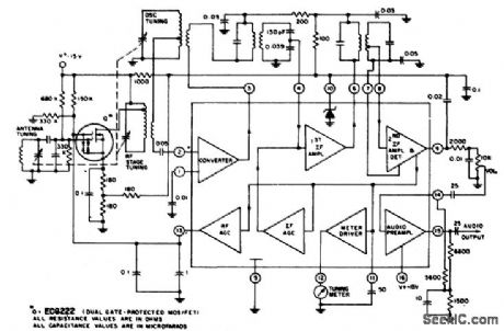
AM broadcast receiver using an ECG787 16-pin DIP.The RF stage is optional,Coils and tuning capacitor can be salvaged from a junk transistor radio or purchased at Radio Shack,The ECG787 provides 75 mV of audio output at the detector that can be fed to any of the audio amplifier circuits shown in this volume,above(courtesy GTE Sylvania Incorporated).PLL FM stereo multiplex decoder using an ECG743 16-pin DIP.The ECG743 features 45 dB channel separation,automatic stereo/mono switching,stereo indicator lamp driver with current limiting,high impedance input with low-impedance output,70 dB SCA rejection and one adjustment alignment.Supply voltage rang is 10 to 16 volts. This circuit is suitable for line-operated and automotive FM stereo receivers below(courtesy GTE Sylvania Incorporated). (View)
View full Circuit Diagram | Comments | Reading(587)
1_watt_AF_amplifier_for_phonographs_with_ceramic_cartridges_using_a_16_ohm_speaker
Published:2009/7/20 2:21:00 Author:Jessie


1-watt AF amplifier for phonographs with ceramic cartridges, using a 16-ohm speaker. Sensitivity is 100 mV for 1-watt output. Supply voltage should be 16 volts (courtesy GTE Sylvania Incorporated). (View)
View full Circuit Diagram | Comments | Reading(569)
REGULATOR_DIODE_STRING
Published:2009/7/20 2:21:00 Author:Jessie
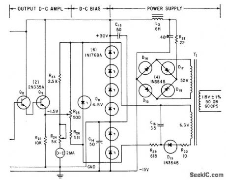
Six 5% silicon regulator diodes operated at 65 ma give +30 v at 90 ma and -15 v of 95 ma. Used with vibration-measuring circuit whose peak reading output drives d-c amplifier Q8-Q9 to give required output current of 2 ma for d-c meter or recorder.-H. A Harriman and W. M. Trenholm, Vibration Measurements with Peak. Reading Circuit, Electronics, 35:20, p 57-59. (View)
View full Circuit Diagram | Comments | Reading(564)
The ABS USB data, SP205, PCM, BCM, instrument part and EBCM/EBTOM circuits of Buick-Regal
Published:2011/7/20 1:36:00 Author:Borg | Keyword: instrument part, Buick-Regal
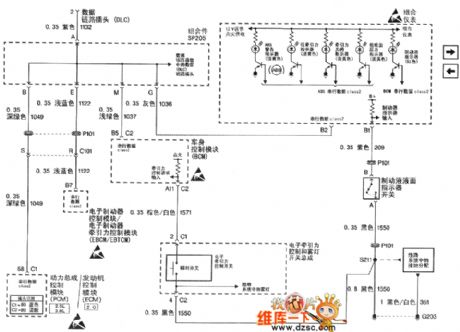
Figure 1. The ABS USB data, SP205, PCM, BCM, instrument part and EBCM/EBTOM circuits of Shanghai GM Buick-Regal
(View)
View full Circuit Diagram | Comments | Reading(801)
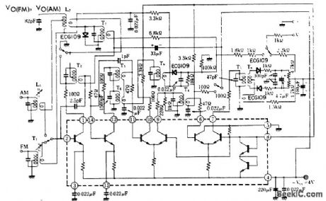
05_watt_audio_amplifier_for_an_AM_FM_radio
Published:2009/7/20 2:20:00 Author:Jessie
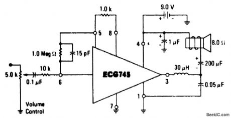
0.5-watt audio amplifier for an AM/FM radio. The ECG745 is an 8-pin DIP (courtesy GTE Sylvania Incorporated ). (View)
View full Circuit Diagram | Comments | Reading(545)
The ABS pulling over switch input and torque circuits of Buick-Regal
Published:2011/7/20 1:38:00 Author:Borg | Keyword: ABS, pulling over switch, Buick-Regal
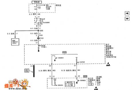
Figure 1. The ABS pulling over switch input and torque circuits of Shanghai GM Buick-Regal (View)
View full Circuit Diagram | Comments | Reading(436)
14_V_TWO_ZENER_REGULATOR
Published:2009/7/20 2:20:00 Author:Jessie
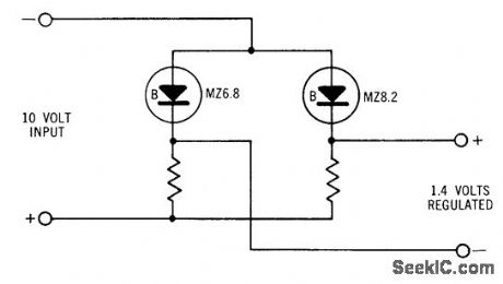
Used to deliver regulated voltage lower thon is normally available with zener diodes. Difference voltage is used for output. Gives excellent temperature compensation because both diodes tend to drift in same direction.- Zener Diode Handbook, International Rectifier Corp., 1960, p 54. (View)
View full Circuit Diagram | Comments | Reading(908)
AM_FM_IF_amplifier_for_455_kHz_and_107_MHz_using_an_ECG1054_14_pin_DIP
Published:2009/7/20 2:20:00 Author:Jessie
AM/FM IF amplifier for 455 kHz and 10.7 MHz using an ECG1054 14-pin DIP. IF coils and transformers are all standard and can be purchased at Radio Shack. Supply voltage is 4 volts (courtesy GTE Sylvania Incorporated). (View)
View full Circuit Diagram | Comments | Reading(626)
The ABS wheel rotating speed sensor and EBOM circuits of Buick-Regal
Published:2011/7/20 1:46:00 Author:Borg | Keyword: rotating speed sensor, Buick-Regal
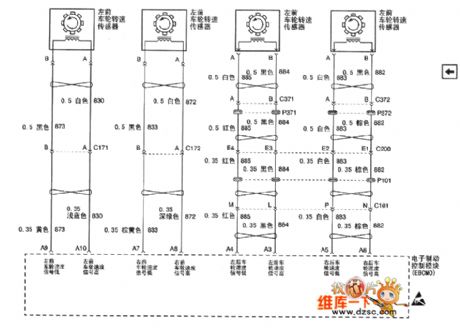
Figure 1. The ABS wheel rotating speed sensor and EBOM circuits of Shanghai GM Buick-Regal (View)
View full Circuit Diagram | Comments | Reading(592)
FAN_SPEED_CONTROLLER
Published:2009/7/20 2:19:00 Author:Jessie
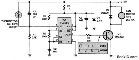
The speed of the fan motor increases as the thermistor gets warmer. The motor is fed with pulses whose duty cycle increases from 34 to 100 percent. (View)
View full Circuit Diagram | Comments | Reading(1032)
AM_broadcast_receiver_using_an_LM3909_chip
Published:2009/7/20 2:19:00 Author:Jessie
AM broadcast receiver using an LM3909 chip. The LM3909 acts as a detector amplifier. It does not oscillate because there is no positive feedback. The receiver is only good for local stations and sensitivity is similar to a crystal set. It will drive a 6-inch loudspeaker. The antenna can be the short version shown, which is 10 to 20 feet long, or the long version, which is 30 to 100 feet. The long one works better (courtesy National Semiconductor Corporation). (View)
View full Circuit Diagram | Comments | Reading(479)
The ABS USB data, grouped instrument and ABS /traction control unit circuit of Buick-MPV (GL8)
Published:2011/7/20 1:51:00 Author:Borg | Keyword: grouped instrument, control unit circuit, Buick-MPV
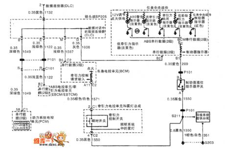
Figure 1. The ABS USB data, SP205, PCM, BCM, grouped instrument and ABS /traction control unit circuit of Buick-MPV (GL8)
(View)
View full Circuit Diagram | Comments | Reading(861)
VARIABLE_FREQUENCY_A_C_REGULATOR
Published:2009/7/20 2:17:00 Author:Jessie
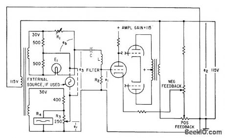
Commercial ballast tube in thermal regulating bridge is used with feedback-stabilized amp lifer and liter to regulate ac voltage source to 0.1%. Used for instrument calibration. Triode oscillator circuit oscillates al series resonant frequency of LC filter, which can be-tuned from 50 to 2,000 cps.-E. A Gilbert, Precision Variable Frequency Power Supply, Electronics, 34:2, p 99-100. (View)
View full Circuit Diagram | Comments | Reading(707)
FM_stereo_multiplex_decoder_using_an_ECG789_16_pin_QIP
Published:2009/7/20 2:17:00 Author:Jessie
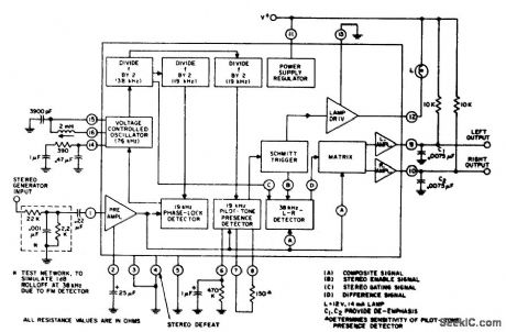
FM stereo multiplex decoder using an ECG789 16-pin QIP. Typical supply voltage is 12 volts; however, the ECG789 can operate over a wide variation of supply voltage up to 16 volts. The internal lamp driver can be made to drive a lamp of hjgher power than the 14 mA one shown by controlling an external NPN or PNP transistor. To drive PNP type, pin 13 is grounded and pin 12 is connected to the base. To drive an NPN type, pin 12 is connected to supply and pin 13 is connected to the base (courtesy GTE Sylvania Incorporated). (View)
View full Circuit Diagram | Comments | Reading(976)
High_gain_107_MHz_FM_limiter_amplifier_detector_for_FM_receivers
Published:2009/7/20 2:16:00 Author:Jessie
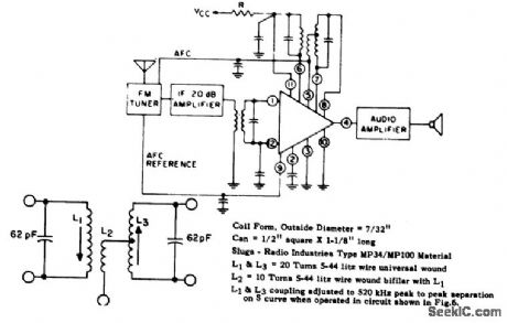
High-gain 10.7 MHz FM limiter/amplifier/detector for FM receivers. Supply voltage should be 30 volts with resistor R being 750 ohms. See lower diagram for specific discriminator information. The bypass capacitor at pin 5 is 0.001,μF.Bypass capacitors at pins 2, 9, 11, and 12 are 0.05μF. The input transformer is a standard 10.7 MHz IF type (courtesy GTE Sylvania Incorporated). (View)
View full Circuit Diagram | Comments | Reading(795)
LIGHTNING_DETECTOR
Published:2009/7/20 2:16:00 Author:Jessie
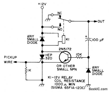
Uses 20-foot wire strung around repeater house to pick up pulses induced by lightning, Keep wire well away from antenna and transmitter. Pulse at SCR gate turns it on and energizes relay that activates signaling device at desired location. Circuit automatically resets itself after capacitor discharges through 10K resistor.-P. A. Stark, Simple Lightning Detector, 73Magazine, April 1973, p85. (View)
View full Circuit Diagram | Comments | Reading(3631)
Complete_107_MHz_FM_IF_system_for_FM_broadcast_receivers_using_an_ECG788_16_pin_DIP
Published:2009/7/20 2:15:00 Author:Jessie
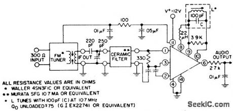
Complete 10.7 MHz FM IF system for FM broadcast receivers using an ECG788 16-pin DIP. The ECG788 chip also has delayed AGC at pin 15 for an RF amplifier, a tuning meter output at pin 13, a mute drive at pin 12, muting sensitivity at pin 5 and an AFC output at pin 7 (courtesy GTE Sylvania Incorporated). (View)
View full Circuit Diagram | Comments | Reading(708)
| Pages:861/2234 At 20861862863864865866867868869870871872873874875876877878879880Under 20 |
Circuit Categories
power supply circuit
Amplifier Circuit
Basic Circuit
LED and Light Circuit
Sensor Circuit
Signal Processing
Electrical Equipment Circuit
Control Circuit
Remote Control Circuit
A/D-D/A Converter Circuit
Audio Circuit
Measuring and Test Circuit
Communication Circuit
Computer-Related Circuit
555 Circuit
Automotive Circuit
Repairing Circuit