
Circuit Diagram
Index 862
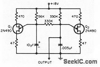
IF_amplifier_for_455_kHz_or_107_MHz
Published:2009/7/20 2:15:00 Author:Jessie
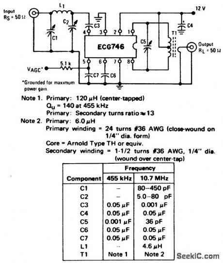
IF amplifier for 455 kHz or 10.7 MHz. See table for component selection (courtesy GTE Sylvania Incorporated). (View)
View full Circuit Diagram | Comments | Reading(704)
The ABS pulling over switch and torque circuit of Shanghai GM Buick-MPV (GL8)
Published:2011/7/20 1:53:00 Author:Borg | Keyword: ABS, pulling over switch, torque circuit
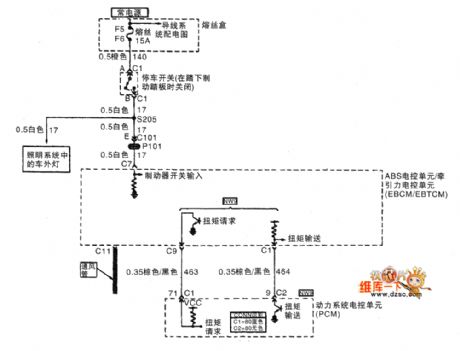
The ABS pulling over switch and torque circuit of Shanghai GM Buick-MPV (GL8)
(View)
View full Circuit Diagram | Comments | Reading(508)
TWO_LEVEL_REGULATION_FOR_12_V_AT_02A
Published:2009/7/20 2:15:00 Author:Jessie
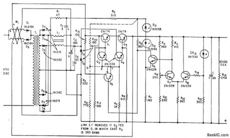
Transformer provides two voltages, one for normal operation and the other to supply current during transients. Storage capacitance is only one-tenth of that needed with conventional series regulator.-F. L. Ward, Novel Bi-Level Regulator Reduces Storage Capacitance, Electronics, 35:32, p 74-75. (View)
View full Circuit Diagram | Comments | Reading(574)
05_watt_AF_amplifier_for_a_phonograph_with_a_ceramic_cartridge
Published:2009/7/20 2:14:00 Author:Jessie
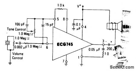
0.5-watt AF amplifier for a phonograph with a ceramic cartridge. The ECG745 is an 8-pin DIP (courtesy GTE Sylvania Incorporated). (View)
View full Circuit Diagram | Comments | Reading(575)
The ABS wheel rotating speed sensor and EBCM/EBTCM circuit of Shanghai GM Buick-MPV (GL8)
Published:2011/7/20 1:56:00 Author:Borg | Keyword: ABS, wheel rotating speed sensor, EBCM/EBTCM
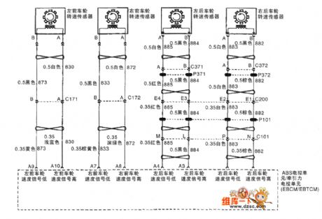
The ABS wheel rotating speed sensor and ABS electric/traction control unit circuit of Shanghai GM Buick-MPV (GL8)
(View)
View full Circuit Diagram | Comments | Reading(895)
MICROPROCESSOR_CONTROL
Published:2009/7/20 2:13:00 Author:Jessie
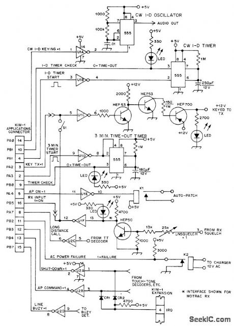
Under pro-gram control, interface for MOS Technology KIM-1 microcomputer turns on transmitter of. repeater when signal arrives at receiver; pro-vides 3-min timer, CW ID timer, and tail or delay at end of transmission; and generates Morse code CW ID. Article gives flow charts and programming for basic functions, along with complete autopatch control routine. CR1 and CR2 are small-signal silicon diodes such as 1N914, U1 and U2 are 7404 TTL hex inverters.-C, M. Robbins, The Microprocessor and Repeater Control, QST, Jan. 1977, p 30-34. (View)
View full Circuit Diagram | Comments | Reading(895)
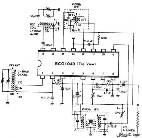
AM_broadcast_tuner_with_BF_amplifier
Published:2009/7/20 2:13:00 Author:Jessie
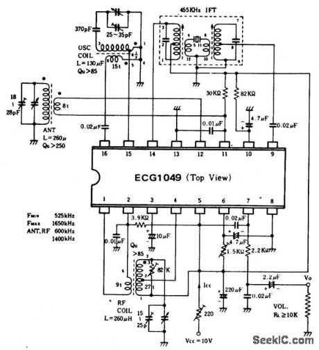
AM broadcast tuner with BF amplifier.All coils and transformers are standard and can be purchased at Radio Shack.The three-section tuning capacitor is also standard.Audio output with 400-hertz modulation at 30% is 80 mV(courtesy GTE Sylvania Incorporated). (View)
View full Circuit Diagram | Comments | Reading(671)
The 2.5L(LBB) and 3.0L(LW9) engine circuit of Shanghai GM Buick-Regal (14)
Published:2011/7/20 2:14:00 Author:Borg | Keyword: engine circuit, Buick-Regal
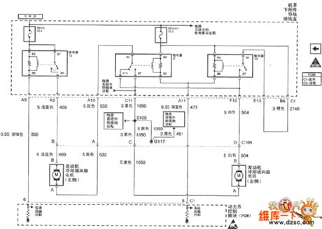
Figure 1. The 2.5L(LBB) and 3.0L(LW9) engine circuit of Shanghai GM Buick-Regal (14) (View)
View full Circuit Diagram | Comments | Reading(490)
VOLTAGE_STABILIZER_USING_FOUR_CONSTANT_CURRENT_DIODES
Published:2009/7/20 2:12:00 Author:Jessie
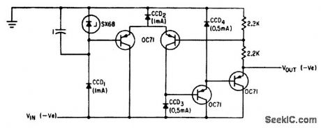
Value of stabilized output voltage can be adjusted by placing potentiometer in parallel with SX68 zener diode and connecting base of Q1 to slider. With this arrangement, magnitude and phase angle of output voltage setting.-T. K. Hemingway, Applications of the Constant-Current Diode, Electronics, 34:42, p 60-63. (View)
View full Circuit Diagram | Comments | Reading(890)
INVERTING_SAIYIPLE_AND_HOLD
Published:2009/7/9 23:29:00 Author:May
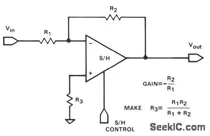
This illustrates another application in which the hookup versatility of a sample-and-hold often elimi-nates the need for a separate op amp and a sample-and-hold module. This hookup will have a some-what higher input-to-output feedthrough during hold than the noninverting connection, since the output impedance is an open-loop value during hold. The feedthrough will (View)
View full Circuit Diagram | Comments | Reading(407)
107_MHz_FM_wide_band_high_gain_IF_amplifier_limiter_using_an_ECG781_8_lead_TO_99
Published:2009/7/20 2:12:00 Author:Jessie
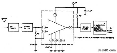
10.7 MHz FM wide-band high-gain IF amplifier-limiter using an ECG781 8-lead TO-99. Supply voltage is 8.5 volts. The circuit provides a voltage gain of 80 dB. Typical sensitivity is 50,mV at 10.7 MHz (courtesy GTE Sylvania Incorporated). (View)
View full Circuit Diagram | Comments | Reading(495)
VARYING_FREQUENCY_OSCILLATOR
Published:2009/7/9 23:29:00 Author:May
Output frequency of alarm tone generator changes continuously. With suitable ampliler and loudspeaker, can easily be heard in noisy environments where single tone or amplitudemodulated tone would go unnoticed.-A. Jnall, Varying-Frequency Warning Alarm, EEE, l2:7, p 25. (View)
View full Circuit Diagram | Comments | Reading(655)
1_watt_phonograph_amplifier_with_an_8_ohm_speaker
Published:2009/7/20 2:11:00 Author:Jessie
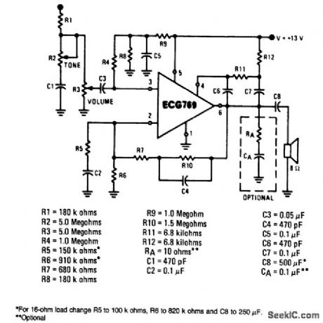
1-watt phonograph amplifier with an 8-ohm speaker. Intended for use with a ceramic cartridge. Sensitivity approximately 450 mV. The gain of the amplifier is determined by (R7+R10)/R5. To change the gain, alter the value of R5 and hold (R7+R10) between 1M and 2.2M. Bass boost can be eliminated by removing C4 and replacing (R7+R10) with a fixed resistor valued at 2.2M (courtesy GTE Sylvania Incorporated). (View)
View full Circuit Diagram | Comments | Reading(744)
Smith_AFC_system_for_an_FM_receiver
Published:2009/7/20 2:10:00 Author:Jessie
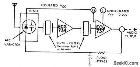
Smith AFC system for an FM receiver. The ECG737 is an FM detector and limiter. It uses quadrature detection and includes a voltage regulator at pin 3. The ECG734 is an FM gain block. This type of circuit is ideal for FM mobile operation (courtesy GTE Sylvania Incorporated). (View)
View full Circuit Diagram | Comments | Reading(615)
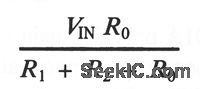
ADJUSTABLE_VOLTAGE_LIMITER
Published:2009/7/9 23:28:00 Author:May
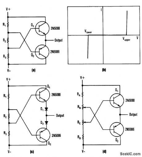
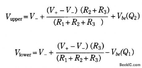
This bipolar voltage clipper can be built with two transistors, two resistors, and two potentiometers.Notice that the maximum p-p range must be ≤ BVebo of the transistors used. The design equations are:
(View)
View full Circuit Diagram | Comments | Reading(718)
AM_broadcast_tuner_with_two_IF_amplifiers
Published:2009/7/20 2:09:00 Author:Jessie
AM broadcast tuner with two IF amplifiers. Audio output with 400-hertz modulation at 30% is 80 mV. All coils, transformers and variable capacitors are standard.The tuning capacitor is a two-section type with the antenna section at 18 to 28 pF and trimmed and the oscillator section at 25 to 35 pF and trimmed. Pads can be purchased at Radio Shack (courtesy GTE Sylvania Incorporated). (View)
View full Circuit Diagram | Comments | Reading(576)
TRANSIENT_PULSE_DETECTOR
Published:2009/7/9 23:28:00 Author:May
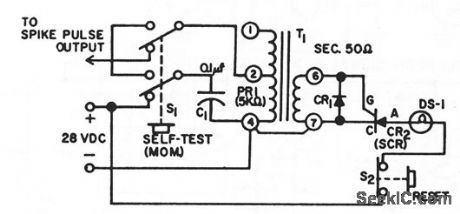
Delermines occurrence of single spike pulse hoving moximum amplitude of 50 v at 2 ma and durotion of 1 millisec. Spike pulse is stepped down by transformer to 5 v at 20 ma, which is sufficident to fire GE C10 scr, causing 28-v lamp to come on. When reset button is pressed, str cuts off, lump goes out, and circuit is ready for another spike. C1 is 0.1 mid and CR1 is IN270.-Transient Spike Pulse Detector, Electronic Circuit Design Handbook, Mactier Pub. Corp., N.Y., p 204. (View)
View full Circuit Diagram | Comments | Reading(830)
READING_SAWTOOTH_CO_NTROLLING_FLIP_FLOP
Published:2009/7/20 2:08:00 Author:Jessie
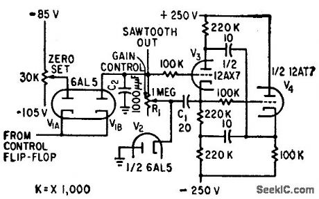
When flip-flop output is negative with respect to zero-set reference voltage, sow tooth output is dropped through diode gate to reference voltage. Start-sawtooth pulse makes output of flip-flop positive.-H. L. Daniels and D. K. Sampson, Magnetic Drum Provides Analog Time Delay, Electronics, 32:6, p 44-47. (View)
View full Circuit Diagram | Comments | Reading(498)
TRACK_AND_HOLD_SAMPLE_AND_HOLD
Published:2009/7/9 23:27:00 Author:May
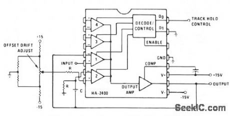
Channel 1 is wired as a voltage follower and is turned on during the track/sample time. If the product of R × C is sufficiently short compared to the period of maximum output frequency, or sample time; Cwill charge to the output level. Channel 2 is an integrator with zero input signal. When channel 2 is then turned on, the output will remain at the voltage across C. (View)
View full Circuit Diagram | Comments | Reading(627)
VARIABLE_AMPLITUDE_TUNNEL_DIODE_OSCILLATOR
Published:2009/7/20 2:07:00 Author:Jessie
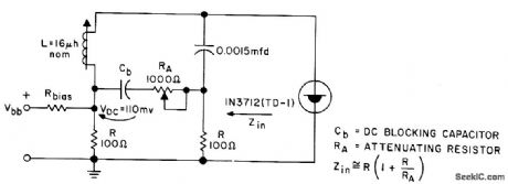
Attenuating resistor RA varies magnitude of oscillator swing, so oscillator operates over limited highly linear portion of diode conductance curve.- Transistor Manual, Seventh Edition, General Electric Co., 1964, p 351. (View)
View full Circuit Diagram | Comments | Reading(825)
| Pages:862/2234 At 20861862863864865866867868869870871872873874875876877878879880Under 20 |
Circuit Categories
power supply circuit
Amplifier Circuit
Basic Circuit
LED and Light Circuit
Sensor Circuit
Signal Processing
Electrical Equipment Circuit
Control Circuit
Remote Control Circuit
A/D-D/A Converter Circuit
Audio Circuit
Measuring and Test Circuit
Communication Circuit
Computer-Related Circuit
555 Circuit
Automotive Circuit
Repairing Circuit