
Circuit Diagram
Index 870
AUDIO_COMPRESSOR_AUDIO_BAND_SPLITTER
Published:2009/7/9 22:31:00 Author:May
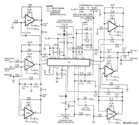
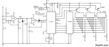
This 2-band compressor splits the audio into high and low frequencies and allows independent adjustment of each. Two active filters drive the two halves of dual voltage controlled amplifier/rectifter IC. Each section has a dynamic range greater than 100 dB. Compression gain slopes are adjustable from 2 to 25 for both audio bands. RB adjusts the threshold amplitude between the two bands. RK1 and R2/C2 control the compressor attack times (10 kΩ and 2 μF, respectively), while the 1.5-MΩ) resistor in the integrator circuit controls the release line. (View)
View full Circuit Diagram | Comments | Reading(2684)
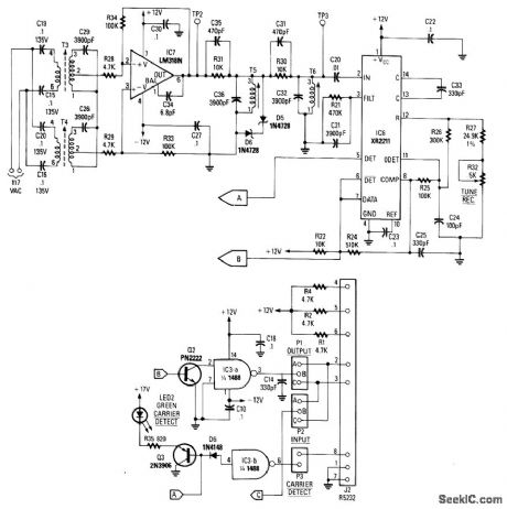
DIGITAL_DATA_LINE_RECEIVER__
Published:2009/7/9 22:29:00 Author:May

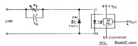
When digital data is transmitted over long lines (longer than 1 meter), proper transfer is often disturbed by the parasitic effects of ground level shifts and ground loops, as well as by extraneous noise picked up along the way. An optocoupler, such as the H11L, combining galvanic isolation to minimize ground loop currents and their concomitant common-mode voltages, with predictable switching levels to enhance noise immunity, can significantly reduce erratic behavior. Resistor RS is programmed for the desired switching threshold, CS is an optional speed-up capacitor, and CR1 is an LED used as a simple diode to provide perfect line balance and a discharge path for CS if the speed-up capacitor is used. (View)
View full Circuit Diagram | Comments | Reading(1129)
The car electric igniter (3)
Published:2011/7/21 21:27:00 Author:qqtang | Keyword: electric igniter
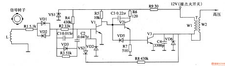
The working principle of the circuit The car electric igniter circuit consists of the synchronous pulse process amplifier, switch booster and feedback circuit, see as figure 7-134.
The synchronous pulse signal generator circuit consists of the signal rotor, electromagnet coil L, resistor R1-R5, resistors C1 and C2, diodes VD1-VD4, the regulated diode VS1 and transistor V1 The switch booster circuit consists of the transistors of V2 and V3, resistors of R6, R7 and R9, diode VD5, capacitors of C3 and C4, booster transformer T and so on. (View)
View full Circuit Diagram | Comments | Reading(1975)
TRANSMITTER_NEGATIVE_KEY_LINE_KEYER
Published:2009/7/9 22:29:00 Author:May
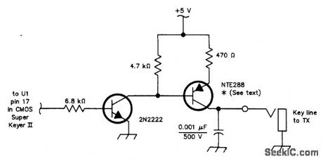
Using an NTE288 (or ECG288, GE223, or SK3434), this circuit can key a negative line up to-300V maximum. Do not use this circuit to key a vacuum-tube amplifier that draws grid current because the keying transistor might be damaged under these conditions. (View)
View full Circuit Diagram | Comments | Reading(643)
CW_KEYER
Published:2009/7/9 22:27:00 Author:May
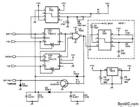
This electronic keyer uses four ICs (five, if the optional sidetone oscillator is desired) and operates from dc sources of 9 to 15V. A 2N2222 is used as a keying transistor. If isolators or more power handling ability is desired, a 6-V relay can be keyed with the 2N2222 and the relay in turn can be used to key the transmitter. (View)
View full Circuit Diagram | Comments | Reading(1314)
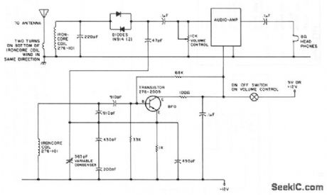
SIMPLE_HAM_BAND_RECEIVER
Published:2009/7/9 22:26:00 Author:May
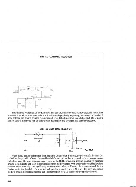

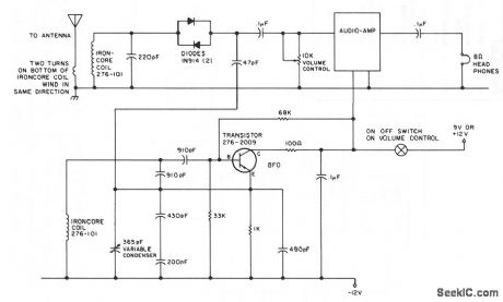
This circuit is configured for the 80m band. The 365-pF, broadcast-band variable capacitor should have a vernier drive with a six-to-one ratio, which makes tuning easier by separating the stations on the dial. A good antenna and ground are also recommended. The Radio Shack iron-core chokes (276-101), used in the bfo part of the circuit, can be calibrated by listening for the bfo signal in a calibrated receiver.
(View)
View full Circuit Diagram | Comments | Reading(1525)
ACOUSTIC_DOPPLER_MOTION_DETECTOR
Published:2009/7/9 22:25:00 Author:May
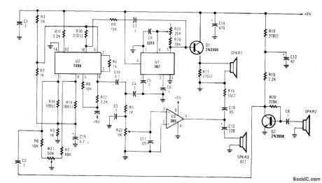
A high-frequency audio signal (15 to 25 kHz) generated by U1 is fed to buffer Q1 and SPKR1. A por-tion is fed to balanced mixer U2. Received audio picked up by SPKR2 (used as a microphone) is amplifted by Q2 and fed to U2. When sound is reflected from a moving object, the Doppler effect will cause an apparent shift in frequency. U2 produces a signal equal to the frequency difference. This is coupled via C16 and gain control R23 to amplifier U3, where the beat note is heard in SPKR3. (View)
View full Circuit Diagram | Comments | Reading(954)
Unipolar_binary_digital_to_voltage_converter_using_an_AD7520_D_A_converter
Published:2009/7/20 3:43:00 Author:Jessie
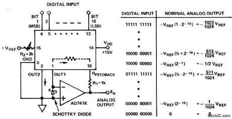
Unipolar binary digital-to-voltage converter (two-quadrant multiplier) using an AD7520 D/A converter. R1 and R2 provide gain adjustment capability (courtesy Analog Devices, Inc.). (View)
View full Circuit Diagram | Comments | Reading(988)
7_watt_AF_power_amplifier_featuring_thermal_shutdown_with_load_connected_to_the_supply_voltage
Published:2009/7/20 3:42:00 Author:Jessie
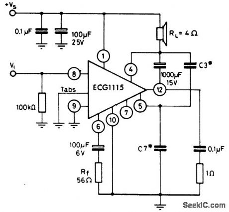
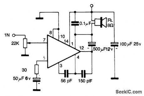
7-watt AF power amplifier featuring thermal shutdown with load connected to the supply voltage. Capacitor C3 is 1500 pF typically with C7 being 5600 pF. Generally C7 should be five times greater than C3. Typical supply voltage is 16 volts for the rated output. Input resistance is 5M. Input voltage is 220 mV PMS. With a supply voltage of 9 volts the output power will be 2.5 watts (courtesy GTE Sylvania Incorporated). (View)
View full Circuit Diagram | Comments | Reading(530)
AC_VOLTMETER
Published:2009/7/9 22:25:00 Author:May
CA081 and CA3140 BiMOS op amp offer minimal loading on the circuits being measured。The wide bandwidth and high slew rate of the CA081 allow the meter to operate up to 0.5 MHz, (View)
View full Circuit Diagram | Comments | Reading(1837)
33_watt_AF_power_amplifier_using_an_ECG1118_14_pin_QIP
Published:2009/7/20 4:33:00 Author:Jessie
3.3-watt AF power amplifier using an ECG1118 14-pin QIP. This circuit is designed for radio application (courtesy GTE Sylvania Incorporated). (View)
View full Circuit Diagram | Comments | Reading(600)
AM_FM_stereo_tuner
Published:2009/7/20 2:58:00 Author:Jessie
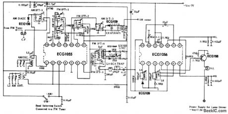
AM/FM stereo tuner. Both ICs are 14-pin DIPs. The ECG1055 is an AM/FM IF amplifier and AM converter, while the ECG1056 is a stereo multiplex demodulator with a composite amplifier, 19 kHz pilot signal filter, a 38 kHz subcarrier generator and either a matix or switching circuit for left and right stereo audio channels (courtesy GTE Sylvania Incorporated). (View)
View full Circuit Diagram | Comments | Reading(1718)
MAGNETRON_INJECTION_ELECTRODE_SUPPLY
Published:2009/7/20 2:57:00 Author:Jessie
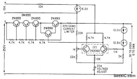
Constclnf-volfc1ge bridge footing on variatble resistor feeds differential amplifier and series regulator. Rheostat setting determines value of regulated output voltage.-S. Prigozy, Designing Special Power Supplies for Voltage-Tunable Oscillators, Electronics, 35:44, p 48-50. (View)
View full Circuit Diagram | Comments | Reading(639)
Composite_AM_FM_IF_amplifier_and_detector_circuitry
Published:2009/7/20 2:57:00 Author:Jessie
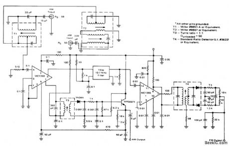
Composite AM/FM IF amplifier and detector circuitry (courtesy Motorola Semiconductor Products Inc.). (View)
View full Circuit Diagram | Comments | Reading(627)
146_MHz_RECEIVER_PREAMP
Published:2009/7/20 2:56:00 Author:Jessie
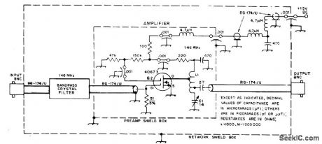
Uses 146-MHz bandpass crystal filter to suppress front-end in-termodulation-distortion products (IMD) in VHF repeater circuits while providing gain of 6-8 dB to overcome filter insertion loss. Also helps front-end overload problems from strong adjacent-channel amateur signals. Filter response is down 40 dB at ±38 kHz and down over 50 dB beyond 60 kHz from filter center frequency. Filter used is Piezo Technology TM-4133VBP.Input and output for filter should be exactly 50 ohms.-J. M. Hood, Monolithic Crystal Filter Application in Amateur VHF Repeaters, QST, July 1975, p 27-29 and 48. (View)
View full Circuit Diagram | Comments | Reading(2137)
22_watt_AF_power_amplifiers_for_low_cost_phonographs_using_an_EGG1112_14_pin_DIP
Published:2009/7/20 2:56:00 Author:Jessie
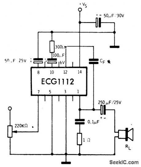
2.2-watt AF power amplifiers for low-cost phonographs using an EGG1112 14-pin DIP. The 2.2-watt rating is based on a 16-ohm load. Recommended supply voltage is 18 volts. Input impedance is 150K. Typical voltage gain is 72 dB. Current drain at maximum output is 175 mA. Capacitor OF can be either 510 pF or 820 pF. With OF at 820 pF the frequency response falls off at about 8 kHz; at 510 pF it extends up to 10 kHz (courtesy GTE Sylvania Incorporated). (View)
View full Circuit Diagram | Comments | Reading(611)
44_watt_audio_power_amplifier_for_a_4_ohm_load
Published:2009/7/20 2:55:00 Author:Jessie
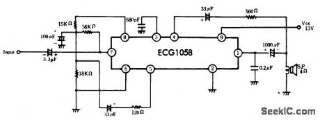
4.4-watt audio power amplifier for a 4-ohm load. The ECG1058 consists of a differential amplifier, a driver amplifier, a ripple filter, an automatic operating point stabilizer and a quasi-complementary SEPP OTL power amplifier circuit. This circuit is particularly good for automotive stereo applications since it is powered by a 13-volt supply. Typical voltage gain at 1 kHz is 45 dB (courtesy GTE Sylvania Incorporated). (View)
View full Circuit Diagram | Comments | Reading(661)
FM_IF_amplifier_detector_and_audio_amplifier_with_1_watt_output
Published:2009/7/20 2:55:00 Author:Jessie
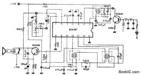
FM IF amplifier detector and audio amplifier with 1-watt output. The ECG1057 is a 14-pin DIP. The circuit shown can be adapted for either 4.5 MHz or 10.7 MHz. Select the IF transformers accordingly. Coils and transformers are standard and can be purchased at Radio Shack (courtesy GTE Sylvania Incorporated). (View)
View full Circuit Diagram | Comments | Reading(1068)
FM_stereo_demodulator_with_integral_Stereo_monaural_switch_75_mA_lamp_driving_capability
Published:2009/7/20 2:54:00 Author:Jessie
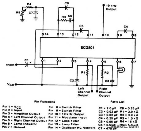
FM stereo demodulator with integral Stereo/monaural switch 75 mA lamp driving capability.Typical supply voltag;is 12 volts but can be operated between 8 and 14 volts. Alignment is simple since there is only one adjustment,R5.Adjust R5 until 19 kHz is read at pin 10 on a frequency counter(courtesy GIE Sylvania Incorporated). (View)
View full Circuit Diagram | Comments | Reading(531)
100_Hz
Published:2009/7/20 2:54:00 Author:Jessie
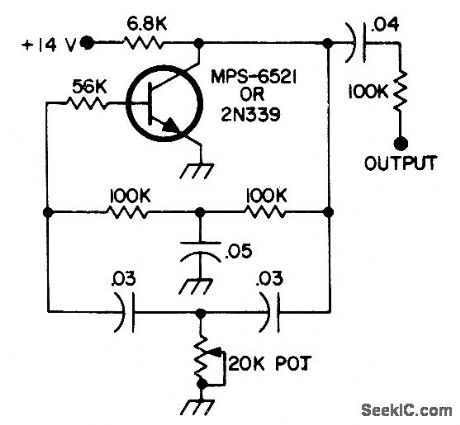
Simple and stable subaudible tone generator serves for access to FM repeaters.Frequency is adjusted to that of repeater with 20K pot. Will operate from car battery.-Circuits, 73 Magazine, Sept. 1973, p 143. (View)
View full Circuit Diagram | Comments | Reading(1022)
| Pages:870/2234 At 20861862863864865866867868869870871872873874875876877878879880Under 20 |
Circuit Categories
power supply circuit
Amplifier Circuit
Basic Circuit
LED and Light Circuit
Sensor Circuit
Signal Processing
Electrical Equipment Circuit
Control Circuit
Remote Control Circuit
A/D-D/A Converter Circuit
Audio Circuit
Measuring and Test Circuit
Communication Circuit
Computer-Related Circuit
555 Circuit
Automotive Circuit
Repairing Circuit