
Circuit Diagram
Index 863
MULTIPLE_INPUT__OVERVOLTAGE__ALARM
Published:2009/7/9 23:27:00 Author:May
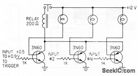
Lamp load of each silicon-contralled switch lights when its input exceeds threshold voliage,to identify input that is responsible for pulling In relay that sounds alarm or shutsdown equipment Lamps aIso serve to suppress rate effect-R.A.Stasior How to suppress Rale Effect in PNPN Devices,Electronics,37:2, p 30-33. (View)
View full Circuit Diagram | Comments | Reading(773)
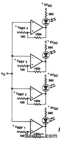
VISABLE_VOLTAGE_INDICATOR
Published:2009/7/9 23:26:00 Author:May
View full Circuit Diagram | Comments | Reading(666)
RECORDING_SAWTOOTH_CONTROLLING_FLIP_FLOP
Published:2009/7/20 2:06:00 Author:Jessie
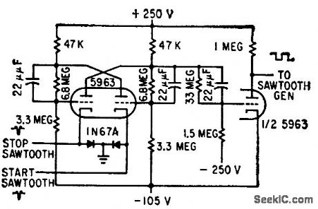
Used for sawtooth generator of magnetic drum recording system.-H. L. Daniels and D. K. Sampson, Magnetic Drum Provides Analog Time Delay, Electronics, 32:6, p 44-47. (View)
View full Circuit Diagram | Comments | Reading(434)
VHF_INTRUSION_ALARM
Published:2009/7/9 23:25:00 Author:May
Based on fact that object moving toward or away from antenna causes phase relationship of radiated and reflected waves to shift through 2 pi radians at antenna for each half-wave length of movement. Varying phase changes amplitude of oscillation, detected by circuit and used to turn on alarm. Drift in oscillator grid voltage activates timing motor which adjusts degree of coupling between oscillator tank and antenna, to make alarm self-adjusting.-G. A.Whitlow, VHF Intrusion Alarm is Self-Adiusting, Electronics, 3235, p 62-66. (View)
View full Circuit Diagram | Comments | Reading(599)
WIDE_RANGE_AC_VOLTMETER
Published:2009/7/9 23:24:00 Author:May
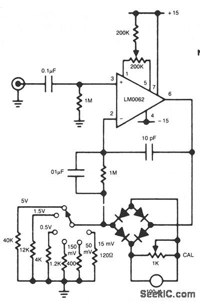
In this circuit, a diode bridge is used as a meter rectifier. The offset voltage is compensated for by the op amp, since the bridge is in the feedback network. (View)
View full Circuit Diagram | Comments | Reading(842)
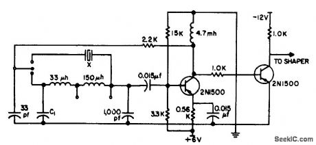
SINE_WAVE_TUNNEL_DIODE_1
Published:2009/7/20 2:05:00 Author:Jessie
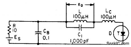
Series filter selects desired frequency and rejects harmonics from pulse-shaped output of basic tunnel-diode relaxation oscillator. Values shown give 0.45 Mc, constant within 0.05 Mc over bias range of 100 to 400 mv.-Wen-Hsiung Ko, Designing Tunnel Diode Oscillators, Electronics, 34:6, p 68-72. (View)
View full Circuit Diagram | Comments | Reading(691)
VU_RECORDER
Published:2009/7/20 2:05:00 Author:Jessie
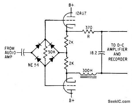
Used to provide permanent records of broadcast speech levels and for checking audio network circuits. Circuit has same rise time, overshoot, frequency response, and recliner characteristics as standard Vu meter.-D. H. McRae, Vu Recorder Has Standard Response, Electronics, 31:17, p 78-82. (View)
View full Circuit Diagram | Comments | Reading(610)
SCR_CAPACITOR_TURN_OFF_CIRCUIT
Published:2009/7/9 23:24:00 Author:May
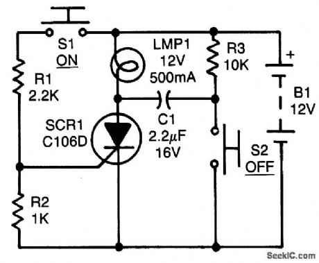
After the SCR tums on, C1 charges up to almost the full supply voltage via R3 and the anode of the SCR. When S2 is subsequently closed, it clamps the positive end of C1 to ground, and the charge on C1 forces the anode of the SCR to swing negative momentarily, thereby reverse-biasing the SCR and causing it to tum off. The capacitor's charge bleeds away rapidly, but it has to hold the SCR's anode negative for only a few ps to ensure turn-off. C1 must be a nonpolarized type. (View)
View full Circuit Diagram | Comments | Reading(1548)
CASSETTE_MOTOR_SPEED_CALIBRATOR
Published:2009/7/9 23:24:00 Author:May
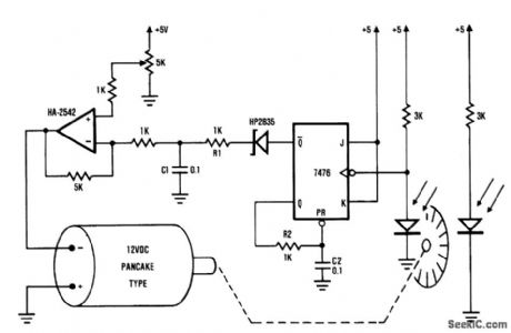
This frequency/voltage converter enables calibrations of cassette-deck speed. It records a steady 1-kHz tone on the cassette deck, and monitors the frequency on the converter. Then play the tone back and adjust the motor speed until you get the same frequency reading on the converter. The frequency/voltage converter can drive an analog meter to indicate small variations in tape speed.
(View)
View full Circuit Diagram | Comments | Reading(1794)
471_MC_TUNNEL_DIODE_CRYSTAL_OSCILLATOR
Published:2009/7/20 2:04:00 Author:Jessie
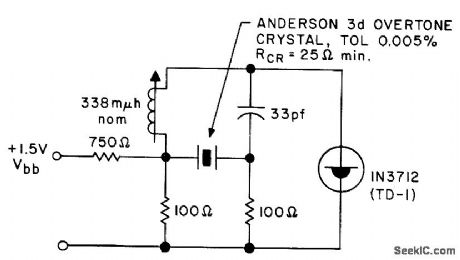
Used in Fire Department service. 0perates within tolerance of quartz crystal from -55 to +85℃ and bias range of 110 to 150 mv for Citizens Band service.- Transistor Manual, Seventh Edition, General Electric Co., 1964, p 353. (View)
View full Circuit Diagram | Comments | Reading(1045)
CHRISTMAS_LIGHT_DRIVER
Published:2009/7/9 23:23:00 Author:May
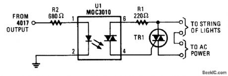
This circuit will enable a CM0S logic chip, such as a 4017 decode driver, to control a string of Christ-mas lights or other lighting. The triac should be rated at 200V and 3A or higher. The 4017 should be powered from at least 10V to ensure adequate drive to the optoisolator. (View)
View full Circuit Diagram | Comments | Reading(1173)
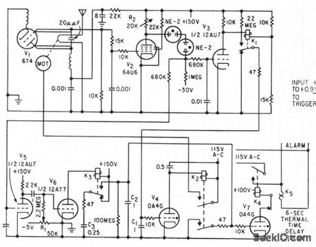
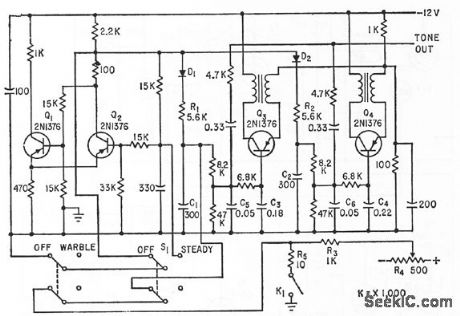
COMPUTER_FAULT_ALARM
Published:2009/7/9 23:22:00 Author:May
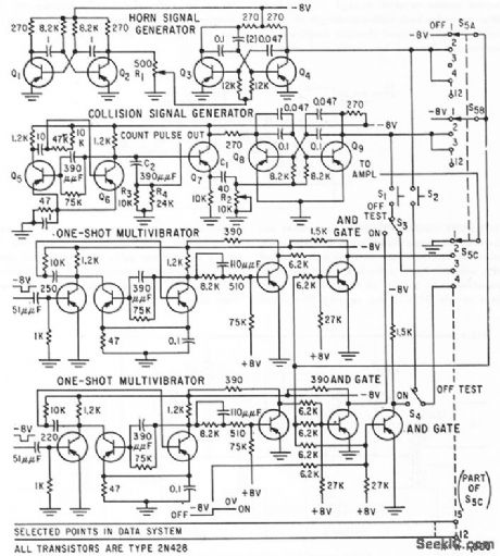
AudibIe alarm system gives distinctive indication of fault loccttion in digitcd computer and data processing equipment. Hom cnd collision signcd sounds are generctted by electronic circuits shown, for monitoring two circuits. Mixing those two signals produces battle stations sound for monitoring third circuit.-S. Fierston, Alarm Circuit Warns of Faults in Digital Systems, Electronics, 32:27, p 48-49. (View)
View full Circuit Diagram | Comments | Reading(687)
10000_1_KV_PULSES_PER_SECOND
Published:2009/7/20 2:03:00 Author:Jessie
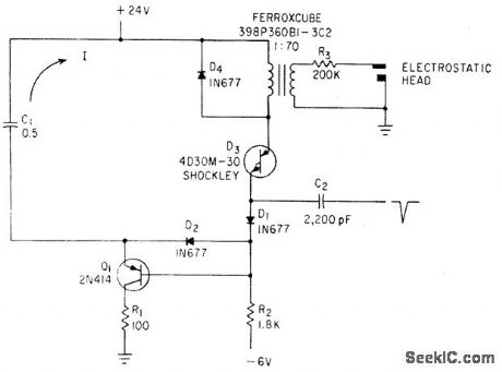
Four-layer diode D3 discharges C1 through pulse transformer and transistor Q1 prevents diode front remaining in conducting state. Used in electrographic recorder.-N. C. Hekimian and P. M. Schmitz, Four-Layer Diode Triggers High-Voltage Pulse Generator, Electronics, 34:26, p 84-85. (View)
View full Circuit Diagram | Comments | Reading(511)
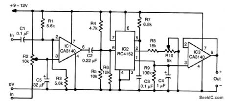
PEAK_PROGRAM_DETECTOR
Published:2009/7/9 23:22:00 Author:May
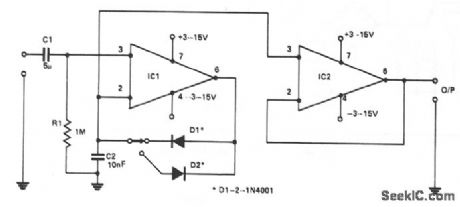
This circuit will allow a multimeter to display the positive or negative peaks of an incoming signal. A 741, IC1, is used in the noninverting mode with R1 defining the input impedance. D1 or D2 will conduct on a positive or negative peak, charging C2 until the inverting input is at the same dc level as the incoming peak. This level will maintain the voltage until a higher peak is detected, then this will be stored by C2. Another 741, IC2, prevents loading by the multimeter. Connected in the noninverting mode as a unity gain buffer, output impedance is less than 1 Ω. This circuit has a useful frequency response from 10 Hz to 100 kHz at ± 1 dB. High linearity is ensured by placing the diodes in the feedback loop of IC1, effectively compensating for the 0.6 V bias that these components require. (View)
View full Circuit Diagram | Comments | Reading(739)
TIMER_IS_AUTOPATCH_KEYER
Published:2009/7/20 2:03:00 Author:Jessie
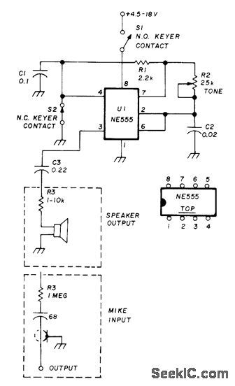
Simple keyer oscillator using NE555 timer was designed for autopatch in repeater having decoder bandpass from 2980 to 3080 Hz. Adjust R2 to 3042 Hz. 0ut-put options for loudspeaker and microphone are shown. Adjust R3 for required input/output level; use variable resistor if desired. Normally closed keyer contacts can also be connected between pin 7 and ground. Supply can be 9-V transistor radio battery.-E. Noll, Circuits and Techniques, Ham Radio, April 1976, p 40-43. (View)
View full Circuit Diagram | Comments | Reading(654)
CRYSTAL_OR_CAPACITOR_OSCILLATOR
Published:2009/7/20 2:02:00 Author:Jessie
Gives high stability from 800 kc to 3 Mc, from 0 to 65℃ with either crystal or capacitor. Optimum operating frequency can be found and utilized by changing capacitor value C1 in range up to 500 pf, while awaiting delivery of CT-cut crystal at desired frequency. -T. Asai, Crystal-or-capacitor Oscillator, EEE, 12:3, p 72. (View)
View full Circuit Diagram | Comments | Reading(731)
STALLED_OUTPUT_DETECTOR
Published:2009/7/9 23:22:00 Author:May
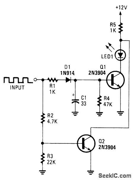
This circuit can be used to detect a stuck out-put or node in a circuit, or a loss of data or pulses.The pulse train charges C1 and biases Q1 on, which lights the LED. If the input remains high, Q2 extin-guishes the LED. (View)
View full Circuit Diagram | Comments | Reading(673)
SIX_ACCESS_TONES
Published:2009/7/20 2:02:00 Author:Jessie
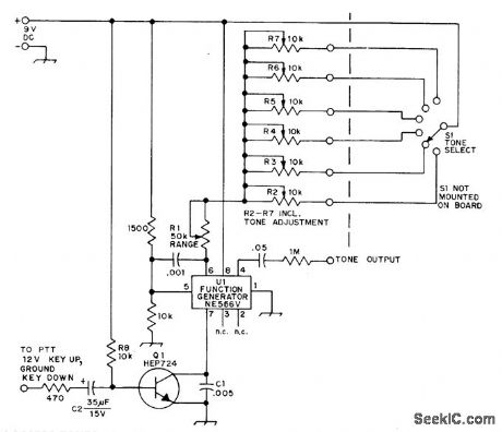
Provides 0.4-s bursts at choice of six audio frequencies, for access to up to six different repeaters. Value of C1 in transistor circuit determines duration of burst. AF oscillator uses Signetics NE566V phase-locked loop, with tone frequencies determined by C1 and R1 plus R2 through R7. To adjust initially, remove Q1 from circuit so oscillator runs continuously, connect frequency counter to junction of 0.05-pF capacitor and 1-megohm resistor, set all pots at minimum, ad just R1 for 2500 Hz, set selector switch to position 1, and adjust corresponding control for desired frequency.Repeat for other pots.-G. M. Dickson, A Tone-Burst Generator for Repeater Access, QST, April 1974, p 30-31. (View)
View full Circuit Diagram | Comments | Reading(530)
ALARM_LAMP_DRIVER
Published:2009/7/9 23:21:00 Author:May
Lamp receives power only when combination of signcds from binary stages and mvbr is correct combination of polarities to represent microwave system fctdt to be indicated by remotely located lamp.-J.B. Bullock, Pulse-Coded Foult Alarm in Microwave Systems, Electronics, 33:1, p 82-84. (View)
View full Circuit Diagram | Comments | Reading(572)
DEGLITCHER
Published:2009/7/9 23:21:00 Author:May
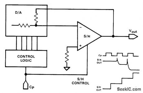
Glitch has been a universal slang expression among electronics people for an unwanted transient con-dition. In D/A converters, the word has achieved semiofficial status for an output transient, which occurs when the digital input addressed is changed. The sample/hold amplifier does double duty, serving as a buffer amplifier as well as a glitch remover, delaying the output by 1/2-clock cycle.
The sample/hold can be used to remove many other types of glitches in a system. If a delayed sample pulse is required, it can be generated using a dual monostable multivibrator IC. (View)
View full Circuit Diagram | Comments | Reading(2384)
| Pages:863/2234 At 20861862863864865866867868869870871872873874875876877878879880Under 20 |
Circuit Categories
power supply circuit
Amplifier Circuit
Basic Circuit
LED and Light Circuit
Sensor Circuit
Signal Processing
Electrical Equipment Circuit
Control Circuit
Remote Control Circuit
A/D-D/A Converter Circuit
Audio Circuit
Measuring and Test Circuit
Communication Circuit
Computer-Related Circuit
555 Circuit
Automotive Circuit
Repairing Circuit