
Circuit Diagram
Index 860
MIDDLEBROOCK_SERIES_STABILIZED_SUPPLY
Published:2009/7/20 2:35:00 Author:Jessie
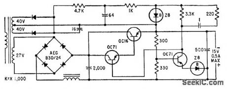
Provides constant 15 v for moderately variable load, with temperature coefficient of 1 my per degree C, 4 my peak-to-peak ripple, and 0.5 amp maximum current.-E. Baldinger and W. Czaja, Designing Highly Stable Transistor Power Supplies, Electronics, 32:39, p 70-73. (View)
View full Circuit Diagram | Comments | Reading(554)
SAMPLE_AND_HOLD_3
Published:2009/7/9 23:31:00 Author:May
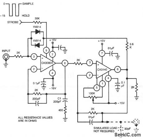
This circuit uses a CA3140 BiMOS op amp as the readout amplifier for the storage capacitor C1, and a CA3080A variable op amp as input buffer amplifier and low feedthrough transmission switch. Offset nulling is accomplished with the CA3140. (View)
View full Circuit Diagram | Comments | Reading(592)
PHONE_RING_REMOTE_CONTROL
Published:2009/7/20 2:33:00 Author:Jessie
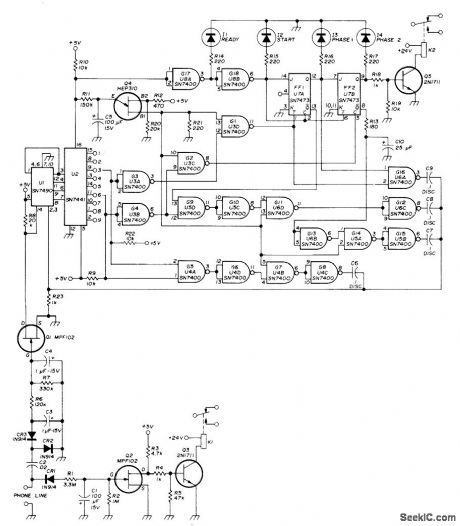
Repeater or other unattended equipment can be turned on or off with ordinary telephone Phone at remote station is called and allowed to ring three times Caller then hangs up, waits 20 s, redials number and lets it ring three times again, then hangs up. Circuit then performs desired control function. Any combination of rings can be used as long as total is less than nine. Decoder U2 is programmed by moving two jumper wires to various outputs of U2. Relay K2 is chosen to give desired momentary, latching, or stepping function. Relay K1 is used for validating phone line, If remote station keying voltage is taken through contacts of K1, interruption of phone line prevents activation of transmitter. C1 stores voltage during brief interruptions such as when phone is ringing. Article gives detailed explanation of ring-counting circuit. LEDs 11-14 indicate status of control sequence and aid in troubleshooting. K1 and K2 are sensitive DPDT relays with 8000-ohm coils. R11 is selected for desired time setting.-R. C. Heptig, Automatic Telephone Controller for Your Repeater, Ham Radio, Nov. 1974, p 44-48. (View)
View full Circuit Diagram | Comments | Reading(837)
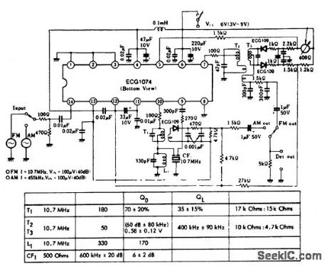
AM_front_end_with_AM_FM_IF_amplifier_and_detector
Published:2009/7/20 2:32:00 Author:Jessie
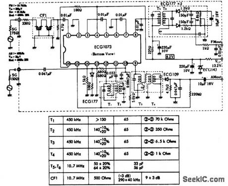
AM front end with AM/FMIF amplifier and detector.ince supply voltage is 13.2 volts,he circuit is ideal for automotive applications.F1 is a 10.7 MHz ceramic filter(courtesy GTE Sylvania Incorporated). (View)
View full Circuit Diagram | Comments | Reading(801)
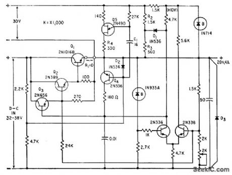
SERIES_RUGULATOR_WITH_TRANSISTOR_PREREGULATOR
Published:2009/7/20 2:31:00 Author:Jessie
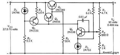
Design procedure is give to meet specification that regulation factor F range from 0.001 for no load to 0.00145 for full load when input voltage varies over range specified. Output varies from 30.7 v to 31.l over temperature range of -50 to +125℃.-Texas Instruments Inc., Transistor Circuit Design, McGraw-Hill, N.Y., 1963, p 160. (View)
View full Circuit Diagram | Comments | Reading(677)
1_watt_phonograph_amplifier_for_ceramic_cartridges_with_16_ohm_speaker
Published:2009/7/20 2:30:00 Author:Jessie
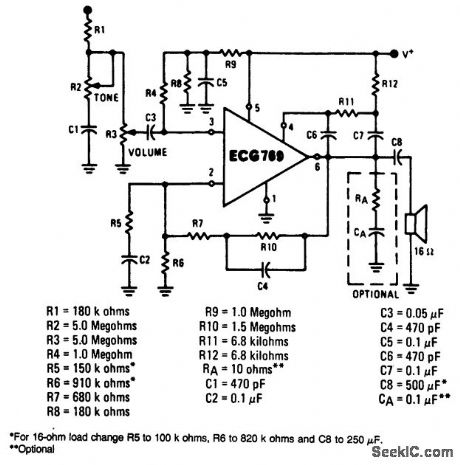
1-watt phonograph amplifier for ceramic cartridges with 16-ohm speaker. See table for component values. Sensitivity is approximately 450 mV. The gain of this amplifier is determined by (R7 + R10)/R5. To alter the gain, change R5 and hold (R7 + R10) between 1M and 2.2M. Bass boost can be eliminated by removing C4 and replacing (R7 + R10) with a fixed resistor value at 2.2M (courtesy GTE Sylvania Incorporated). (View)
View full Circuit Diagram | Comments | Reading(863)
Record_playback_amplifier_for_cassette_and_portable_tape_recorders
Published:2009/7/20 2:30:00 Author:Jessie
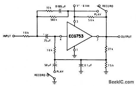
Record/playback amplifier for cassette and portable tape recorders (courtesy GTE Sylvania Incorporated). (View)
View full Circuit Diagram | Comments | Reading(520)
The 300W electric transformer made of IR2151 and IR840
Published:2011/7/21 0:48:00 Author:Borg | Keyword: electric transformer
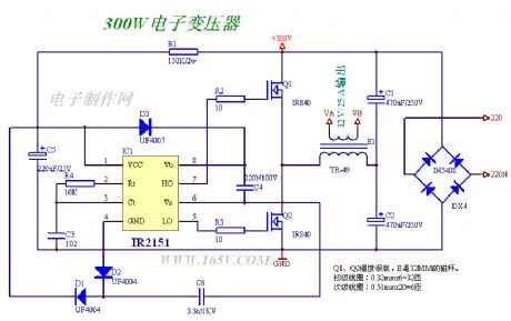
The 300W electric transformer is made of IR2151 and IR840.This transformer can work normally without regulation.
(View)
View full Circuit Diagram | Comments | Reading(6001)
AC_MOTOR_CONTROL
Published:2009/7/20 2:29:00 Author:Jessie
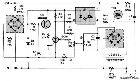
This circuit controls fans and other ac motors that have less than 1/4 horsepower and lack a centrifugal starting switch. It works by controlling the effective voltage in the ac circuit and governs both starting and varying load conditions. A ramg voltage is developed across capacitor C1. The voltage across C1 will vary the delay in turning on SCR1. The amplitude of that voltage is controlled manually by R8 for adjusting the motor speed, and by a preadjusted potentiometer (R9) to provide governing action (R9 should be adjusted to provide maximum regulation). The level of the ramp, relative to the firing voltage of Q1, is set by R12. The value of R1, must be chosen to accomrnodate the load; a lower value might be more satisfactory for a larger motor. Transformer T1 can be wound with a primary of 25 turns of 26-gauge wire and a secondary of 200 turns. Alternatively, any small transformer with a turns ratio of approximately 1:10 will do. (View)
View full Circuit Diagram | Comments | Reading(0)
AM_FM_IF_amplifier_and_detector_with_tuning_meter
Published:2009/7/20 2:29:00 Author:Jessie
AM/FM IF amplifier and detector with tuning meter.AF output is about 10 mV for 400-hertz modulation at 30%.Typical voltage gain is 90 dB for FM and 80 dB for AM(courtesy GTE Sylvania Incorporated). (View)
View full Circuit Diagram | Comments | Reading(939)
TRANSDUCTORS_STABILIZE_HIGH_POWER_RECTIFIER
Published:2009/7/20 2:27:00 Author:Jessie
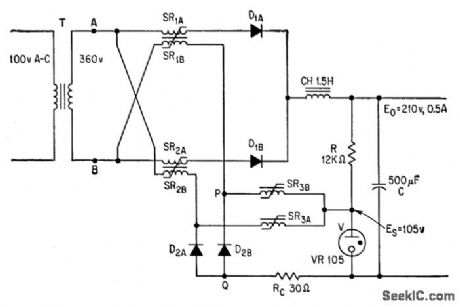
Rectangular-loop saturable reactors SR in single-phase power supply hold output voltage constant within l% at load currents of 0 to 20 amp and line voltage variations of 50%. Choice of components de-determines power capacity.-T. Kurimura and K. Yamamura, New Way to Use Saturable Reactors: Stabilizing High-Power Rectifiers, Electronics, 36:21, p 61-66. (View)
View full Circuit Diagram | Comments | Reading(502)
1_watt_class_B_audio_amplifier_with_preamplifier
Published:2009/7/20 2:27:00 Author:Jessie
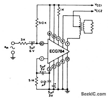
1-watt class B audio amplifier with preamplifier. Supply voltage VCC1 and VCC2 are 9.0 volts and 12.0 volts, respectively. Sensitivity is 45 mV. Power gain is 75 dB. Input resistance is 55K. Signal-to-noise ratio is 66 dB. Use a standard class B audio output transformer with the appropriate speaker load (courtesy GTE Sylvania Incorporated). (View)
View full Circuit Diagram | Comments | Reading(784)
SOLID_STATE_DRILL_SPEED_CONTROL
Published:2009/7/20 2:27:00 Author:Jessie
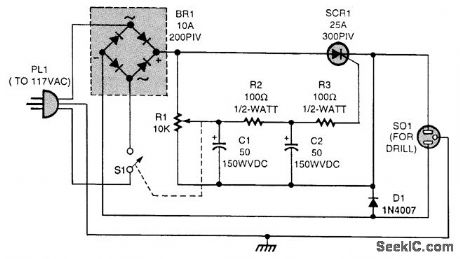
Add this circuit to a single-speed drill to make the speed variable. The bridge rectifier (BR1) provides the full-wave pulsing direct current for the SCR switc (SCR1); BR1 should be rated at 200 PIV and have a current rating of 10 A, while SCR1 should have a PIV of 300 V and a current rating of 25 A. Diode D1 is used to counter the back voltage developed by the drill motor; D1 can be rated at 2 A. The speed of the drill is varied by R1. (View)
View full Circuit Diagram | Comments | Reading(1142)
The ADV7175 and ADV7176 digital video encoding integrated circuits
Published:2011/7/20 1:32:00 Author:Borg | Keyword: digital, video encoding, integrated circuits
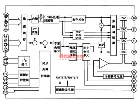
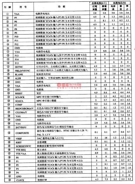
1.pin functionsADV7175 and ADV7176 integrated circuits support many standards of CCIR601/624/656 and SMPE170M, which is in I2C control method, and it can convert the YCRCB video data of 8 or 16-bit into Y, U and V in the patten of 4:4:4, and the 4 internal lObitDAC can output R, G and B, or Y, U and V, or S-VHS and Y/C or mixed video signals. It contains the low-pass filter, color control circuit YUV, RGB matrix circuit, brightness double sampling circuit, image-text TV units and so on.
(View)
View full Circuit Diagram | Comments | Reading(652)
SIREN_POWER_AMPLIFIER
Published:2009/7/9 23:31:00 Author:May
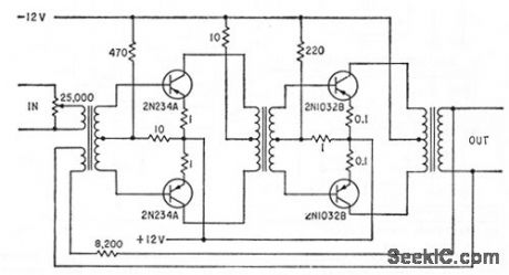
Four-transistor class AB audio amplifier delivers 200 w to four loudspeakers. Standby power drain is 12 w.Input is obtained from warble generator.-W.F. Ferguson, High-Powered Audio Alarm Systems, Electronics, 33:16, p 70-72. (View)
View full Circuit Diagram | Comments | Reading(652)
4_watt_class_A_audio_amplifier_using_an_ECG755_audio_driver_IC
Published:2009/7/20 2:26:00 Author:Jessie
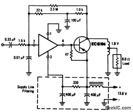
4-watt class A audio amplifier using an ECG755 audio driver IC. This audio amplifier is ideal for automotive applications. The ECG755 is a 4-lead package and is designed to drive a PNP power output transistor such as the EGG104 (courtesy GTE Sylvania Incorporated). (View)
View full Circuit Diagram | Comments | Reading(738)
SHORT_CIRCUIT_PROTECTION
Published:2009/7/20 2:25:00 Author:Jessie
Series regulator has automatic pulsing-type short-circuit protection. D1, R2, and R3 form constant. current prelimiting circuit, and Q4 is shut-off transistor. Unijuunction transistor Q5 pulses continuously. D2 completes discharge path of C1 through R4 when Q5 fires.-A. G. Lloyd, Overload Protection for Transistor Voltage Regulators, Electronics, 33:52, p 56-59. (View)
View full Circuit Diagram | Comments | Reading(1811)
ADF_PHASEMETER
Published:2009/7/20 2:25:00 Author:Jessie
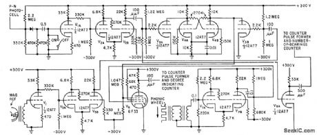
Input signals are squared by Schmitt triggers, differentiated, and changed to unidirectional pulses that drive flip-flop V4 to produce pulse whose length is proportional to bearing of transmitter. 500-cps signal from phonic wheel is sharpened by Schmitt trigger V7 and used to indicate length of bearing pulse in degrees by modulating the pulse in V6. One output goes to decade counter chain that counts total number of degrees.-J. F. Hatch and D. W. G. Byatt, Direction Finder with Automatic Readout, Electronics, 32:16, p 62-64. (View)
View full Circuit Diagram | Comments | Reading(623)
STEPPER_MOTOR_DRIVER
Published:2009/7/20 2:24:00 Author:Jessie
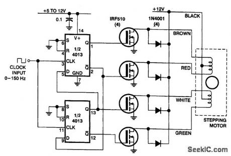
In this circuit, four IRF510 power FETs are driven by a CMOS counter to generate the necessary two-phase drive quadrature. Although ICs are available to do this, this approach is handy for the experimenter because it uses commonly available parts. The stepper motor was taken from a discarded floppy-disk drive. (View)
View full Circuit Diagram | Comments | Reading(7629)
SUBAUDIO_TONES
Published:2009/7/20 2:23:00 Author:Jessie
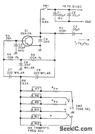
Six-channel subaudible encoder uses twin-T oscillator covering 93 to 170 Hz. Tones are adjustable with 20-turn 10K trimpots. Used with 2-meter amateur transmitters to access and maintain signal through repeater having subaudible tone decoder, When transmitted signal opens up receiver of repeater, subaudible tone on incoming audio closes relay and permits transmitter to key up and repeat signal, Choice of tones permits use of different repeaters in given area. For 93-107 Hz, use 12K for RX; for 98-116 Hz, use 8.2K; and for 114-170 Hz, use jumper. Article gives construction details.-W. G. Moneysmith, Subaudible Tone Encoder, 73 Magazine, Oct. 1977, p 52-53. (View)
View full Circuit Diagram | Comments | Reading(739)
| Pages:860/2234 At 20841842843844845846847848849850851852853854855856857858859860Under 20 |
Circuit Categories
power supply circuit
Amplifier Circuit
Basic Circuit
LED and Light Circuit
Sensor Circuit
Signal Processing
Electrical Equipment Circuit
Control Circuit
Remote Control Circuit
A/D-D/A Converter Circuit
Audio Circuit
Measuring and Test Circuit
Communication Circuit
Computer-Related Circuit
555 Circuit
Automotive Circuit
Repairing Circuit