
Circuit Diagram
Index 851
RUGGED_DESIGN_FOR_OCEANOGRAPHY
Published:2009/7/20 1:32:00 Author:Jessie

Can drive low-impedance recording galvanometer for long periods without auxiliary power. Bilateral symmetry of push-pull circuit using matched 2N65 transistors optimizes linearity and thermal stability. Although designed for d-c operation, response is fiat within 2 db up to 50 kc.-W. G. Von Dom, Transistor D.C Amplifier for Rugged Use in Field, Electronics, 33:1, p 85. (View)
View full Circuit Diagram | Comments | Reading(1221)
DUAL_TIME_CONSTANT_TONE_DECODER
Published:2009/7/20 1:31:00 Author:Jessie

Exar XR-567 PLL system is connected as de-coder having narrow bandwidth and fast response time. Circuit has two low-pass loop filter capacitors,C2 and C'2. With no input, pin 8 is high,Q1 is off, and C'2 is out of circuit. Filter then has only C2, which is kept small for minimum response time. When in-band input tone signal is detected, pin 8 goes low, Q1 turns on, and C'2 is in parallel with C2 to give narrow bandwidth. Supply voltage can be 5-9 V.- Phase-Locked Loop Data Book, Exar Integrated Systems, Sunnyvale, CA, 1978, p 41-48. (View)
View full Circuit Diagram | Comments | Reading(1247)
TRACING_CAUSES_OF_LAB_LINE_TRANSIENTS
Published:2009/7/20 1:29:00 Author:Jessie

Circuit responds to single pulse having rise time as short as 1 microsec, and records average value of line voltage. Transients greater than preset trigger level pass through diode gate and trip mono, giving current pluse that drives chart recorder pin.-F. Trainor, Transient Recorder Monitors Power Linesto Protect Circuits, Electronics, 34:29, p 74-75. (View)
View full Circuit Diagram | Comments | Reading(976)
DUAL_TONE_DECODER
Published:2009/7/20 1:29:00 Author:Jessie

Used in communication systems where control or other information is transmitted as two simultaneous but separate tones Circuit uses two Exar XR-567 PLL units in parallel, with resistor and capacitor values of each PLL decoder selected to provide desired center frequencies and bandwidth requirements supply voltage is 5-9V.- Phase-Locked Loop Data Book. Exar Integrated systems,Sunnyvale,CA,1978,p41-48. (View)
View full Circuit Diagram | Comments | Reading(1312)
PEAK_READING_CIRCUIT
Published:2009/7/20 1:26:00 Author:Jessie

Recovers analog voltage from modulated sawtooth waveform of magnetic-drum recorder.-H. L. Daniels and D. K. Sampson, Magnetic Drum Provides Analog Time Delay, Electronics, 32:6, p 44-47. (View)
View full Circuit Diagram | Comments | Reading(931)
AUTOMATIC_SENSITIVITY_CONTROL_FOR_VIDICON
Published:2009/7/20 1:25:00 Author:Jessie

Positive-going blanked video on grid of video amplifier output stage V3A serves to produce negative agc voltage that increases with camera signal, to reduce gain of first video amplifier stage V2A when light input to vidicon camera increases.-P. C.Kidd, Automatic Sensitivity Control for Vidicon TV Camera, Electronics, 35:6, p 52. (View)
View full Circuit Diagram | Comments | Reading(1791)
GATED_AMPLIFIER_DRIVES_FERRITE_CORES
Published:2009/7/20 1:24:00 Author:Jessie
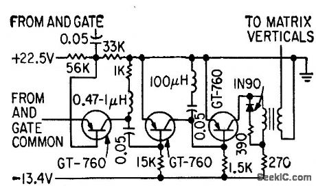
Used in shockproof recorder in which each amplifier drives a line of six cores. Interrogation of cores releases stored information for processing.-C. P. Hedges, Digital Recorder Holds Data After Shock, Electronics, 32:12, p 60-62. (View)
View full Circuit Diagram | Comments | Reading(948)
SATELLITE_RECORDER_AND_TRANSMITTER
Published:2009/7/20 1:16:00 Author:Jessie


Primary video signal bandwidth is 0 to 240 cps. Direct-record system uses 290-cps sub carrier for reproducing d-c component of signal, giving 50-cps lower sideband. Upper sideband (530 cps) is suppressed. Transmitter uses crystal-controlled 108-Mc Hartley oscillator, feeding 1 w to antenna.-R. Hanel et al, Tracking Earth's Weather with Cloud-Cover Satellites, Electronics, 32:18, p 44-49. (View)
View full Circuit Diagram | Comments | Reading(1280)
MAGNETIC_DRUM_WRITE_AMPLIFIER
Published:2009/7/20 1:12:00 Author:Jessie

Power amplifier is followed by impedance-changing device that converts voltage waveform at output of flip-flop into corresponding cur rent waveform for low-impedance recording head of magnetic memory drum, for Manchester recording with 220 ma peak-to-peak.-A. J. Strassman and R. E. Keeter, Clock Track Recorder For Memory Drum, Electronics, 32:41, p 74-76. (View)
View full Circuit Diagram | Comments | Reading(1110)
BANDPASS_AMPLIFIER_DRIVES_RECORDER
Published:2009/7/20 1:08:00 Author:Jessie
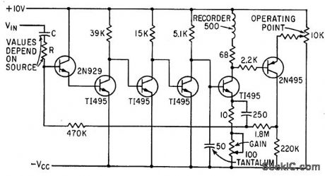
Feedback from final stage to input sets bias level of direct-coupled ac amplifier having current-derived stabilization, for driving re carder over range of 0.2 to 5 cps, with no bulky capacitors.-P. Laakmann, Direct Coupling Shrinks Amplifier Size and Cost, Electronics, 36:12, p 66-68. (View)
View full Circuit Diagram | Comments | Reading(1058)
SHOCKPROOF_FERRITE_CORE_RECORDER
Published:2009/7/20 1:05:00 Author:Jessie

Cores retain stored data even alter 6,000-9 shock. Each transistor encodes decimal digit into two binary digits. Beam-switching decade counter makes Q1 to Q10 count in succession, to energize the lye outputs that pulse cores through gated amplifiers.-C. P. Hedges, Digital Recorder Holds Data After Shock, Electronics, 32:12, p 60--62. (View)
View full Circuit Diagram | Comments | Reading(909)
SOUND_TRACK_DRIVE
Published:2009/7/20 1:02:00 Author:Jessie

Dual-input amplifier drives 10-ohm recording galvanometer for variable-area optical sound track of 16.mm sound-on-film camera. Con be mounted directly on camera. Requires only two 6-V nickel-cadmium cells.-E. M. Tink, Transistorizing 16-Mm Tv Remote Film Camera, Electronics, 32:3, p 58-59. (View)
View full Circuit Diagram | Comments | Reading(973)
FREQUENCY_SYNTHESIZER
Published:2009/7/20 0:56:00 Author:Jessie

Three oscillators oscillator in synthesizer provide frequency increments of 1 kc from 2 to 30 mc, to replace local oscillator operation in double-conversion ssb receiver.-J. E. MacDowell, Stable Frequency Synthesizer Replaces Sideband Converter, Electronics, 35:25, p 41-43. (View)
View full Circuit Diagram | Comments | Reading(928)
SIX_TRANSISTOR_9_V_BROADCAST
Published:2009/7/20 0:55:00 Author:Jessie

Nominal sensitivity is 20 microvolts per meter, rated power output 500 mw, and battery drain 10 ma.- Transistor Manual, Seventh Edition, General Electric Co., 1964, p 295. (View)
View full Circuit Diagram | Comments | Reading(743)
UNNEUTRAIZED_MOS_FET
Published:2009/7/10 1:40:00 Author:May
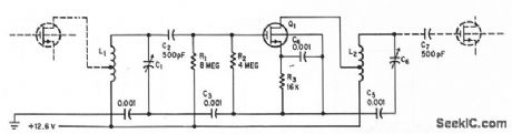
Low draim-gate capacitance is needed for high power gains above 2 Mc from common-source mos fet.-G.G.Luettgenau and S. H. Barnes, Designing With Low-Noise MOS FETs: A Little Different But No Harder, Electronics, 37:31, p 53-58. (View)
View full Circuit Diagram | Comments | Reading(439)
GEIGER_COUNTER
Published:2009/7/20 0:45:00 Author:Jessie

Simple basic monitor provides continuous audio end visual indications of radioactive materials in industrial areas. If recording is required, four leads at right are connected to 10-cps keep-alive mvbr and triode output stage for driving recorder. Will handle count rates up to 10,000 per minute. Strobotron V3 in pulse equalizer provides visual indications.-R. L. Ives, Geiger Radiation Monitor Indicates Continuously, Electronics, 31:43, p 93-95. (View)
View full Circuit Diagram | Comments | Reading(0)
HEE_HAW_ELECTRONIC_SIREN
Published:2009/7/10 1:40:00 Author:May

The oscillator based on IC2 is responsible for producing the sound. Its output is connected to the base of TR1, which amplifies it to drive the speaker. Resistor R4 is included in the circuit to limit the current through TR1 to a safe and reasonable level. The oscillation frequency of IC2 is partially dependent on the values of R3 and C2. Another factor that governs the frequency of oscillation is the magnitude of voltage fed to pin 5 of IC2. If a voltage of varying magnitude is fed to pin 5, the internal circuitry of the IC is forced to reset at a different rate, which changes the frequency.IC1 is also connected as an oscillator,but it runs much slower than IC2: around 1 Hz. Each time the IC triggers, the voltage at pin 3 goes high. As pin 3 is connected to pin 5 of IC2, this forces IC2 to change its note. That produces the hee-haw sound of the siren. (View)
View full Circuit Diagram | Comments | Reading(949)
RADIATION_ALARM
Published:2009/7/20 0:39:00 Author:Jessie

Input is from multiplier phototube having anthracene scintillation crystal on its window. Signals are amplified by Q1, Q2, and Q3, and fed to counter flip-flop Q4-Q5. Flip-f1ip output goes to logarith-mic count circuit whose output level is indi-cared by microammeter. When output exceeds predetermined level, alarm circuit closes relay that actuates audible and visual alarms.-H. E. DeBolt, How Radiation Monitor Guards Nuclear Navy, Electronics, 33:4, p 43-45. (View)
View full Circuit Diagram | Comments | Reading(978)
PERIOD_TO_VOLTAGE_CONVERTER
Published:2009/7/10 1:39:00 Author:May


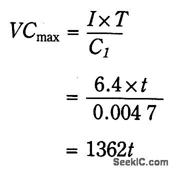
ICA,R1, R2, R3, and Q1 form a current source. The current that charges C1 is given by:
The input signal drives ICD. Because ICD's positiveinp ut (V+)is slightly offset to +0.1V, its steady state output will be around + 13 V. This voltage is sent to ICC through D2, setting ICC's output to + 13 V.Therefore, point D is cut off by D1, and C1 is charged by the current source. Assuming the initial voltage on C1 is zero, the maximum voltage (VCmax) is given by:
If f=1 ms, then VCmax = 362 V.
When the input goes from low to high, a narrow positive pulse is generated at point A. This pulse becomes - 13 V at point B, which cuts off D2. ICC's V+ voltage becomes zero. The charge on C1 will be absorbed by ICC on in a short time. The time constant of C2 and R5 determines the discharge period-about 10 ps. ICB is a buffer whose gain is equal to (R8+R9)÷R9-1.545. ICD's average votiage will be (1362fx1.545)÷2=1052t. R10 and C3 smooth the sawtooth waveform to a dc output. (View)
View full Circuit Diagram | Comments | Reading(691)
250_MC_12_W_POWER_AMPLIFIER
Published:2009/7/10 1:39:00 Author:May

Commonemitter circuits operating class C serve for driver and parallel-connected power amplifier transistors.Total gain is 12 db.-N.Downs and B.van Sutphin, Solid-State Transmitter Ready for UHF Telemetry,Electronics,37:17,p 76-80. (View)
View full Circuit Diagram | Comments | Reading(601)
| Pages:851/2234 At 20841842843844845846847848849850851852853854855856857858859860Under 20 |
Circuit Categories
power supply circuit
Amplifier Circuit
Basic Circuit
LED and Light Circuit
Sensor Circuit
Signal Processing
Electrical Equipment Circuit
Control Circuit
Remote Control Circuit
A/D-D/A Converter Circuit
Audio Circuit
Measuring and Test Circuit
Communication Circuit
Computer-Related Circuit
555 Circuit
Automotive Circuit
Repairing Circuit