
Circuit Diagram
Index 843
ELECTRONIC_BIRD_CHIRPER
Published:2009/7/10 2:26:00 Author:May

Transistors Q1 and Q2 form the two halves of a free-running multivibrator whose frequency is determined by the voltage across C8. That capacitor is charged and discharged by closing and opening switch S1. Transistors Q3 and Q4 make up a VFO. The output of the free-running multivibrator frequency modulates the Q3/Q4 oscillator, causing the chirping bird sound. The number of chirps per second is determined by the frequency of the Q1/Q2 multivibrator, which also varies. The pitch of the chirps is determined by C5 and C6. (View)
View full Circuit Diagram | Comments | Reading(1277)
FM_stereo_processor
Published:2009/7/19 22:58:00 Author:Jessie

FM stereo processor. Supply voltage is typically +12 volts. The ECG720 has the functions of a 19 kHz amplifier, frequency doubter, stereo indicator lamp driver, audio mute, stereo/mono switch, and stereo demodulator. it also permits adjust-able stereo channel separation (courtesy GTE Sylvania Incorporated). (View)
View full Circuit Diagram | Comments | Reading(0)
B_FIELD_MEASURER
Published:2009/7/10 2:26:00 Author:May


This circuit develops an output voltage that is proportional to the magnetic induction, B, flowing through its probe's coil. You must size the coil to give a full-scale, 10-V output for your maximum expected magnetic-induction intensity.
For a given value of B (in tesla) and output voltage, VOUt:
where A is the effective area or your coil in m2 (A = number of turns × average area of each turn), R is the resistance of the coil and the probe, and C is the value of the capacitor. Notice that C should be a low-leakage polypropylene or Teflon device.
For most practical applications that measure a magnetic field in the air, the coil will be either tiny or very thin. If R=1kΩ, C=1μF, and the coil is 100 turns with a mean area per turn of 1 cm2, then the circuit's output will be 1 mV/gauss (1T= 104G).
To use the circuit, push the reset button and place the probe in an area that you know is devoid of magnetic fields. Be sure to avoid magnets and iron. Then, put the probe into the field to be measured and read the V0UT with a voltmeter. Finally, calculate the B field's intensity using the equation.
When constructing the instrument, guard the op amp's inputs from undesirable currents at the minus input. For full-scale outputs, use a ±15-V supply for the op amp. (View)
View full Circuit Diagram | Comments | Reading(553)
CABLE_DRIVING_AMPLIFIER
Published:2009/7/10 2:24:00 Author:May

Used between wideband integrator and l85-ohm cable. With voltage gain of 3, bandwidth is l8 Mc without overshoot for pulse signcds.-S.Berglund and so Westerlund,Probes for Plosma Research with Wideband Integrators,Electronics,35:24,p 44-45. (View)
View full Circuit Diagram | Comments | Reading(537)
TEMPERATURE_COMPENSATED_DARLINGTON
Published:2009/7/10 2:23:00 Author:May
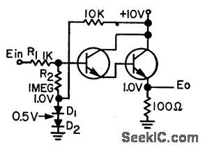
Modiled Darlington includes two diodes and additional resistor. With these, temperature changes up to 50℃ have no effect on output.-R. C. Going, Tempercature-Stctbilized Darlington, EEE, 11:7, p 28-29. (View)
View full Circuit Diagram | Comments | Reading(546)
CHUG_CHUG
Published:2009/7/10 2:23:00 Author:May

A CA3240 dual MOSFET-input device is used as a white-noise source. Op amp IC2 is used as a driver stage for the push-pull output stage formed by Q5 and Q6. Transistors Q2, Q3, and Q4 form a variable-frequency multivibrator. R11, the speed control, is used to control the multivibrator's frequency. The output is differentiated by C8 and applied to modulator transistor Q1, through D1 and R7. Transistor Q1 modulates the gain of the output amplifier stage by changing the impedance to ground, through R6 and C4.When the multivibrator's frequency is reduced using R11, C8 discharges slowly, creating a sound similar to escaping steam from a stopped locomotive.To find the proper value for R3, short Q1's collector to ground. Then, increase the value of R3 until the current drain from the power supply is less than 60 mA. Then remove the short from Q1. To see if the device is operating properly, close switch S1 and reduce the resistance of R11. Wait 10 seconds, then rotate R11 slowly. You should hear a sound similar to a steam locomotive picking up speed. (View)
View full Circuit Diagram | Comments | Reading(683)
160_MC_750_MW_POWER_STAGE
Published:2009/7/10 2:22:00 Author:May

Pi matching networks at input and output optimize tronsistor performonce in class C operation. Ef-ficiency is 25% snd 3-db bandwidth is 15 Mc,Texas Instruments Inc., solid-State Communications, McGraw-Hill, N.Y., 1966,p 318. (View)
View full Circuit Diagram | Comments | Reading(530)
A_continuous_15_V_indicator
Published:2009/7/19 22:58:00 Author:Jessie

This LM3909 circuit shows a continuously appearing indicator light that is powered by 1.5 V. Duty cycle and frequency of the current pulses to the LED are increased (from that of Fig. 12-43B) until the average energy supplied provides sufficient light. At frequencies above 2 kHz, even the fastest movement of the light source or the observer's head will not produce significant flicker. This indicator draws about 12 mA from the 1.5-V battery, and is not intended as a long-life system. (View)
View full Circuit Diagram | Comments | Reading(677)
SECONDARY_EMISSION_PENTODE_CATHODE_FOLLOWER
Published:2009/7/10 2:21:00 Author:May

Circuit is enhanced by connecting dynode bock to cathode. Uses degenerative feedback, to achieve high-performance impedance transformation. Can be used to match high-impedance source to low-impedonce load.-E. J. Martin, Jr., How to Use the Secondary-Emission Pentode, Electronics, 33:41, p 60-63. (View)
View full Circuit Diagram | Comments | Reading(605)
100_KC_MAGNETOSTRICTIVE_ROD_CONTROL_
Published:2009/7/19 22:58:00 Author:Jessie

Oscillator Q1 can be adjusted to within 0.1 cps of desired frequency by adjusting length and center thickness of rod made from modified Elinvar constant-modulus material positioned between coils. Emitter-follower Q2 minimizes pulling by variable load. -T. A O. Gross, New Magnetic Rods Simplify Circuits, Electronics, 35:28, p 62-66. (View)
View full Circuit Diagram | Comments | Reading(810)
COLPITTS_1_to_20_MHz_CRYSTAL_OSCILLATOR
Published:2009/7/10 2:21:00 Author:May

This is a simple Colpitts crystal oscillator for 1 to 20 MHz, can be easily made from junk-box parts(provided that a crystal is handy). (View)
View full Circuit Diagram | Comments | Reading(7067)
FM_stereo_processor
Published:2009/7/19 22:57:00 Author:Jessie

FM stereo processor. Supply voltage is typically +12 volts. The ECG718 is a 14-pin DIP with the functions of a 19 kHz amplifier, frequency doubler, stereo indicator lamp driver, audio mute, stereo/mono switch, and stereo demodulator (courtesy GTE Sylvania Incorporated). (View)
View full Circuit Diagram | Comments | Reading(1192)
ELECTRONIC_MUSIC_MAKER
Published:2009/7/10 2:20:00 Author:May

This electronic muslc maker uses an astable oscillator circuit that is controlled by a photocell.Thelight falling on the photo cell controls the tone.By mounting the circuit h a box,you can control lightreading PC1 with your hand. (View)
View full Circuit Diagram | Comments | Reading(712)
FOUR_TRANSISTOR_REFLEX
Published:2009/7/19 22:57:00 Author:Jessie

Nominal sensitivity is 200 microvolts per meter at 5 mw reference power output. Maximum power output is 75 mw, and total battery drain is 17 ma.- Transistor Manual, Seventh edition, General Electric Co., 1964, p 291. (View)
View full Circuit Diagram | Comments | Reading(520)
FUZZ_BOX
Published:2009/7/10 2:20:00 Author:May

The 741's maximum gain of 20,000 is pushed to nearly 3 million dB, and therefore distorts the output. That distortion provides the fuzz sound.The level is dropped by clipping the two diodes. (View)
View full Circuit Diagram | Comments | Reading(2091)
TRACKED_CURRENT_LIMITING
Published:2009/7/19 22:57:00 Author:Jessie

Simultaneous limiting scheme for both sections of National dual tracking regulator depends on output cur-rent of positive regulator. Voltage drop produced across R1 by positive regulator brings Q1 into conduction, with positive load current I1 increasing until voltage drop across R2 equals negative current-limit sense voltage. Negative regulator will then current-limit, and positive side will closely follow negative output down to level of about 700 mV.-T. Smathers and N. Sevastopoulos, LM125/LM126/LM127 Precision Dual Tracking Regulators, National Semiconductor, Santa Clara, CA, 1974, AN-82, p 13. (View)
View full Circuit Diagram | Comments | Reading(631)
CATHODE_EOLLOWER_WITH_099963_GAIN
Published:2009/7/10 2:20:00 Author:May
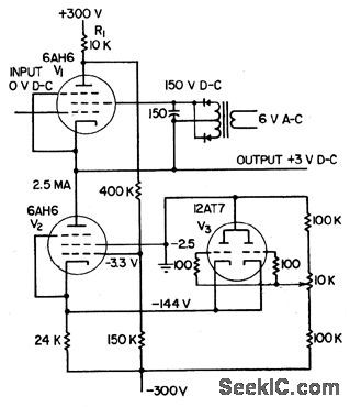
Used to couple high-impedance source to low-impedance output without attenuating or loading source signal. Output impedance is 50 ohms and respomse is lat within 3 db front d-c to 250 kc. Circuit delivers outputs from -140 to +210 v at -0.8 to +2 ma.Feedback through pentade helps maintain unity gain.-Cathode-Follower Gain Approaches Unity, Electronics, 31:1, p 94-96.
(View)
View full Circuit Diagram | Comments | Reading(577)
UNIJUNCTION_TRANSISTOR_OSCILLATOR
Published:2009/7/19 22:57:00 Author:Jessie

If circuit is broken at X, discharge current of C1 can be used to shut off transistor stage. -A. G. Lloyd, Overload Protection for Transistor Voltage Regulators, Electronics, 33:52, p 56-59. (View)
View full Circuit Diagram | Comments | Reading(727)
SOUND_EFFECTS_GENERATOR
Published:2009/7/10 2:19:00 Author:May

A variable clock-pulse generator is made up of two sections of IC1 (a 4069 CMOS hex inverter), R1, 51, and capacitors C1 through C6. By adjusting R1 and switching one of the capacitors into the circuit, the clock's pulse rate can be varied over a wide range.The TL507C converts analog signals-in this case the output of IC3, an LM386 audio amplifier-into digital signals. The conversion is accomplished using the single-slope method; it involves comparing an internally generated ramp signal to the analog input signal and a 200-mV reference voltage.The square-wave output from the a/d converter is fed to IC3 through a network consisting of R2, R3, and C7. Resistor R2 controls the amplitude of the pulses. Resistor R3 and capacitor C7 form a variable tone-control filter and a differentiator circuit that converts a square wave into a spiked waveform. That waveform is amplified by IC3, and the resulting output is fed back into the analog input of IC2, as well as to an 8-Ω speaker. By adjusting R1 and selecting one of the six capacitors with S1-thus varying the clock frequency-and by varying R2 and R3, you can produce many sounds. (View)
View full Circuit Diagram | Comments | Reading(0)
Continuity_and_coil_checker
Published:2009/7/19 22:57:00 Author:Jessie

Using this circuit, a short (up to about 1000) across the test probes provides enough power to produce audible oscillation. In this circuit, the LM3909 is connected as an audio oscillator. By probing two values in quick succession, small differences (such as between a short and 5Ω) can be detected by differences in the tone. A novel use of this circuit is found in setting the timing of certain types of motorcycles. A different tone can be hoard if there is a short (or no short) in the low-resistance primary of the ignition coil (a difference between a 1 -Ω resistor and a 1 -Ω inductor can be detected). Quick checks of transformers and motors can also be made with this simple circuit. National Semiconductor Linear Applications Handbook, 1991, p 399 (View)
View full Circuit Diagram | Comments | Reading(601)
| Pages:843/2234 At 20841842843844845846847848849850851852853854855856857858859860Under 20 |
Circuit Categories
power supply circuit
Amplifier Circuit
Basic Circuit
LED and Light Circuit
Sensor Circuit
Signal Processing
Electrical Equipment Circuit
Control Circuit
Remote Control Circuit
A/D-D/A Converter Circuit
Audio Circuit
Measuring and Test Circuit
Communication Circuit
Computer-Related Circuit
555 Circuit
Automotive Circuit
Repairing Circuit