
Circuit Diagram
Index 841
Warning_flasher_light
Published:2009/7/19 23:26:00 Author:Jessie

Warning flasher light. This device is handy to have around boats, cars, and camp sites. The circuit is a two-stage direct-coupled transistor amplifier connected as a free-running multivibrator. Both flash duration and flash interval can be adjusted by R1 (courtesy General Electric Company). (View)
View full Circuit Diagram | Comments | Reading(767)
SIMPLE_TRANSISTOR_OSCILLATOR
Published:2009/7/19 23:26:00 Author:Jessie

Current gain is stabilized against transistor variation. Can be used over collector voltage range of 2 to 24 V. Oscillation occurs at frequency at which there is 360° total phase shift, 180° of which is furnished by grounded-emitter amplifier and 180° by high-pass network. 5K pot adjusts frequency from about 200 to 400 cps.- Tansistor Manual, Seventh Edition, General Electric Co., 1964, p 206. (View)
View full Circuit Diagram | Comments | Reading(1047)
VOLTAGE_ADAPTER
Published:2009/7/19 23:15:00 Author:Jessie

Bench power supply provides ±12 V and +5 V from single regulated 24-V source, for use with many ICs. Both t2-V supplies can be adjusted in same direction by varying 24-V source or in opposite directions by adjusting 1K pot. RI is used to decrease power dissipated in LM309K voltage regulator and is normally 2.2 ohms.-J. A. Plat, Voltage Adapter for MSI/LSI Circuits, Ham Radio, March 1978, p 115. (View)
View full Circuit Diagram | Comments | Reading(746)
Whooper_siren
Published:2009/7/19 23:14:00 Author:Jessie

This circuit uses two LM3909s, one as a tone generator and one as a ramp generator, to produce a whooper sound that is somewhat like the electronic sirens that are used on city police cars, ambulances, and airport crash wagons. The rapid modulation makes the tone seem louder for the same amount of power input. The tone generator is similar to that of the Fig. 12-55 circuit, except that the pushbutton is replaced by a rapidly rising and falling modulating voltage that is produced by the ramp generator. National Semiconductor Linear Applications Handbook 1991, p 402, (View)
View full Circuit Diagram | Comments | Reading(699)
CHATTER_JAMMER
Published:2009/7/19 23:14:00 Author:Jessie

Can be used to create pleasing tone at level that drowns out ambient noises, to permit concentration on problem while others are talking in vicinity.-J. Leeb, A Chatter Jammer Circuit, EEE, 10:11, p 31. (View)
View full Circuit Diagram | Comments | Reading(681)
MOSFET_chopper_with_extended_range_of_±3_volts
Published:2009/7/19 23:13:00 Author:Jessie

MOSFET chopper with extended range of ±3 volts (courtesy Motorola Semiconductor Products Inc.).
(View)
View full Circuit Diagram | Comments | Reading(887)
Fire_siren
Published:2009/7/19 23:13:00 Author:Jessie

This LM3909 circuit produces a rapidly rising wail upon pressing the button, and a slower coasting down sound upon release. If it is desirable to have the tone stop sometime after the button is released, an 18-kΩ resistor can be placed between pins 8 and 6 of the LM3909. The sound is then much like that of a motor-driven siren, National Semiconductor Linear Applications Handbook, 1991 p. 402.
(View)
View full Circuit Diagram | Comments | Reading(1961)
LOAD_ISOLATING_3_35_MC_OSCILLATOR
Published:2009/7/19 23:13:00 Author:Jessie
Refined version of Lampkin variable r-f oscillator for dual-conversion receiver gives uniform output over band and sufficient stability for single-sideband reception after 30-see warmup.-E. Robberson, R-F Oscillator has improved Stability, Electronics, 36:32, p 62-63. (View)
View full Circuit Diagram | Comments | Reading(585)
TONE_BURST_OSCILLATOR
Published:2009/7/19 23:12:00 Author:Jessie
Consists of variable-frequency magnetically coupled mvbr, with two magnetic cores driven by battery-powered transistors. Injection of current or voltage from solar cell or other transducer affects mvbr reset, to give frequency change over range of 5 to 15 kc.-R. W. Rochelle, Cyclops Cores Simplify Earth-Satellite Circuits, Electronics, 31:9, 56-63. (View)
View full Circuit Diagram | Comments | Reading(671)
_5V_WITH_PROTECTION_
Published:2009/7/19 23:12:00 Author:Jessie

Switching- type short-circuit protection network uses R7 connected to Schmitt trigger Q6-Q7. Ground is provided by Q7 which is normally conducting. ff out-put of regulator is short-circuited, current through Q1 increases; at predetermined limit, a6 conducts and cuts off Q7 breaking ground connection of R7 and thus cutting off Q3 Power transistorQ1 is also cut of, and output current begins to decrease. When load current drops below another predetermined level, Q6 again goes off and Q7 turns on to begin another ON/OFF cycle, with switching process continuing until short-circuit is removed.-H. S, Raina and R. K. Misra, Novel Circuit Provides Short Circuit Protection, EDN Magazine, June 5, 1974, p 84. (View)
View full Circuit Diagram | Comments | Reading(941)
Electronic_
Published:2009/7/19 23:11:00 Author:Jessie

With this circuit, the LM3909 oscillates at the speaker-cone free-air resonance point. That is, if the speaker is in an enclosure with a higher resonant frequency than the speaker, this becomes the frequency at which the circuit oscillates. An educational audio-demonstration device, or simply an enjoyable toy, has been fabricated as follows. A roughly cubical box of about 64 3 was made with one end able to slide in and out like a piston. The box was stiffened with thin layers of pressed wood, etc. Speakers, circuit, battery, and all were mounted on the sliding end, with the speaker facing out through a 21/4 hole. A tube was provided (21/2 long, 5/16 ID) to bleed air in and out as the piston was moved while not affecting resonant frequency. Minimum volume with the piston in was about 10 3. Slide tones can be generated, or a tune played, by properly positioning the piston part and working the push button. National Semiconductor Linear Applications Handbook 1911 p 401. (View)
View full Circuit Diagram | Comments | Reading(657)
FOUR_TRANSISTOR_REFLEX_PORTABLE
Published:2009/7/19 23:11:00 Author:Jessie
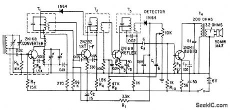
Second if stage doubles as audio amplifier to give five-stage performance.-E. Gottlieb, Transistor Reflex Circuit Trims Receiver Costs, Electronics, 31:1, p 66-68. (View)
View full Circuit Diagram | Comments | Reading(784)
Series_chopper_using_an_N_channel_JFET
Published:2009/7/19 23:10:00 Author:Jessie

Series chopper using an N-channel JFET (courtesy Motorola Semiconductor Products Inc.). (View)
View full Circuit Diagram | Comments | Reading(491)
1000V_AT_100W
Published:2009/7/19 23:10:00 Author:Jessie

Two Delco DTS-723 transistors in series function as pass element of regulator in which differential amplifier Q1-Q2 senses output voltage and compares it with reference voltage at base of O2. Difference signal is amplified by Q3-Q4 for feed to Q5. 12-V regulated supply is referenced to high side of output voltage through R2. R1 is chosen so regulator shuts down when load current reaches 120 mA and triggers Schmitt trigger Q8-Q9 which fires SCR. When overload is removed, circuit returns to normal operation. Input voltage range of 1200-1500 V gives 0.1% regulation at full load.- 1000-Volt Linear DC Regulator, Delco, Kokomo, IN, 1974, Application Note 45. (View)
View full Circuit Diagram | Comments | Reading(771)
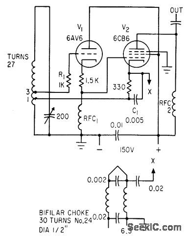
STABLE_OSCILLATOR
Published:2009/7/19 23:09:00 Author:Jessie

Excellent frequency and amplitude stability is accomplished by eliminating all grid current in tank circuit and by isolating tank from driving tube by means of resistive degeneration. If very pure sine wove is required, grid of V1 should be coupled to high-impedance load that is equivalent constant resistance, because either reacyive or variable loads will impair stability.-J. C. Davis, Stable Oscillator Circuit, EEE, 11:2, p 26. (View)
View full Circuit Diagram | Comments | Reading(847)
Morse_code_set
Published:2009/7/19 23:09:00 Author:Jessie

In this circuit, the LM3909 (connected as an oscillator) drives speakers at both sending and receiving ends, simultaneously. National semiconductor, Linear Applications Handbook, 1991 p 400 (View)
View full Circuit Diagram | Comments | Reading(0)
FOUR_LAYER_DIODE_OSCILLATOR
Published:2009/7/19 23:07:00 Author:Jessie

If circuit is broken at X, discharge current of C1 can be used to shut off transistor stage.-A. G. Lloyd, Overload Protection for Transistor Voltage Regulators, Electronics, 33:52, p 56-59. (View)
View full Circuit Diagram | Comments | Reading(667)
Water_seepage_alarm
Published:2009/7/19 23:07:00 Author:Jessie

This LM3909 oscillator circuit can detect water seepage in darkrooms, laundry rooms,etc., and can be used on potentially damp floors with complete safety (because there is no connection to the power line), Also,the standby battery drain of about 100μA yields a battery life that is close to shelf life. The circuit operates as a multivibrator,which starts at about 1 Hz and oscillates faster as more leakage passes across the sense electrodes.The sensor consists of two electrodes(6 or 8 inches long)spaced about 1/8″apart.Two strips of stainless steel on insulators,or the appropriate zig - zag path cut in the copper cladding of a PC board can be used The sensor should be built into the base of the box In which the circuits are packaged.The bare PC board between the copper-sensing areas should be coated with warm wax so that moisture on the floor(not the moisture absorbed by the board)is detected.The circuit and sensor can be tested by simply touching a damp finger to the electrode gap.National Semiconductor Linear Applications Handbook 1991,p400 (View)
View full Circuit Diagram | Comments | Reading(2343)
VOLTAGE_TUNABLE_CARCINOTRON_CONTROL
Published:2009/7/19 23:07:00 Author:Jessie
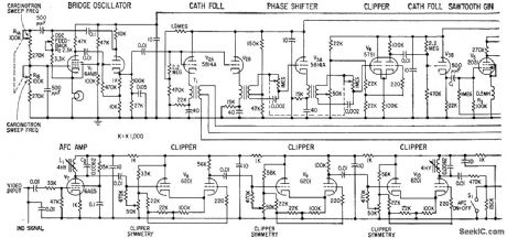
Used with superheterodyne receiver to provide continuous frequency coverage from 30 Mc to 75,000 Mc by means of harmonic mixing.-C. H. Currie, Carcinotron Harmonics -. Boost Receiver Range, Electronics, 32:9, p 58-61. (View)
View full Circuit Diagram | Comments | Reading(599)
±15V_SYMMETRICAL_AT_1A
Published:2009/7/19 23:06:00 Author:Jessie

Connectionshown gives same lineand load regulation characteristics as for individual regulators. D1 ensures start-up of LM340K.15 under worst-case conditions of common load and 1.A load current over full temperature range.- Linear Applications, Vol. 2, National Semiconductor, Santa Clara, CA, 1976, AN-103, p 8. (View)
View full Circuit Diagram | Comments | Reading(948)
| Pages:841/2234 At 20841842843844845846847848849850851852853854855856857858859860Under 20 |
Circuit Categories
power supply circuit
Amplifier Circuit
Basic Circuit
LED and Light Circuit
Sensor Circuit
Signal Processing
Electrical Equipment Circuit
Control Circuit
Remote Control Circuit
A/D-D/A Converter Circuit
Audio Circuit
Measuring and Test Circuit
Communication Circuit
Computer-Related Circuit
555 Circuit
Automotive Circuit
Repairing Circuit