
Circuit Diagram
Index 840
7413_MC_CRYSTAL_REPLACES_LOST_MICRO_WAVE_CARRIER
Published:2009/7/19 22:33:00 Author:Jessie

To prevent noise interference during signal losses due to fading, carriet resupplies oscillator, and amplifier replaces lost carrier, within 0.1 millisec. Q1 and Q2 are switched from cutoff when carrier is needed. Resistor RF in series with crystal lowers its Q to insure rapid starting. -Microwave Relay Designing with Traveling-Wave Tubes, Electronics, 35:3, p 40-43. (View)
View full Circuit Diagram | Comments | Reading(739)
40000_BITS_PER_SEC_OVER_PHONE_LINE
Published:2009/7/19 22:33:00 Author:Jessie

For interconnecting computers, one-transistor line driver und wave shaper permit transmitting 40,000 bits per second up lo half a mile over standard voice-grade phone lines. Three-transistor line receiver and pulse slicer receive data.-R. M. Lee, Speeding Digital Data Over Phone Lines, Electronics, 36:39, p 30-31.
(View)
View full Circuit Diagram | Comments | Reading(1273)
Micropower_voltage_to_frequency_converter
Published:2009/7/19 22:32:00 Author:Jessie

This circuit produces a 0- to 10-kHz output in response to a 0- to 5-V input, with a maximum current consumption of only 90μA. To calibrate, apply 50 mV and select the value at the C1 input for a 100-Hz output. Then, apply 5 V and trim the input potentiometer for a 10-kHz output. Linear Technology Corporation, 1991 AN45 15. (View)
View full Circuit Diagram | Comments | Reading(0)
F_M_TRANSMITTER
Published:2009/7/19 22:32:00 Author:Jessie

Provides 250 mw at 92 Mc, for use with balloon-borne ionizing radiation detectors. Variable-frequency oscillator can be used because only moderate stability is required.-D. Enemark, Transistors Improve Telemeter Transmitter, Electronics, 32:11, p 136-137. (View)
View full Circuit Diagram | Comments | Reading(674)
10_KC_SINGLE_TRANSISTOR_COLPITTS
Published:2009/7/19 22:32:00 Author:Jessie

Total temperature drift rate is only 0.035%/℃, determined by coil core material. For higher frequency stability, frequency-determining network should be buffered from amplifier. - Transistor Manual, Seventh Edition, General Electric Co., 1964, p 210. (View)
View full Circuit Diagram | Comments | Reading(2039)
AM_radio
Published:2009/7/19 23:21:00 Author:Jessie
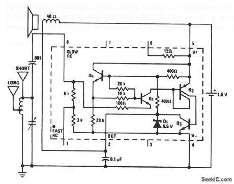
This circuit uses the LM3909 as a basic AM radio (chapter 2). The tuned circuit is a standard AM-radio ferrite antenna coil (loopstick with a tap 40% of the turns from one end) and a 360-pF tuning capacitor). The short antenna is 10 to 20' and the long antenna is 30 to 100'. Notice that this radio does not oscillate, and tuning is only as good as a simple crystal set. Because of the low power drain, the circuit will operate continuously for about a month on a single D flashlight cell, and drive a 6 speaker. National Semiconductor, Linear Applications Handbook, 1991 p 405. (View)
View full Circuit Diagram | Comments | Reading(0)
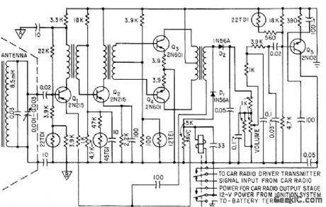
TUNER_FOR_A_M_F_M_PORTABLE
Published:2009/7/19 23:21:00 Author:Jessie

R-f amplifier Q1, mixer Q2, and local oscillator Q3 are all switched to perform same functions on f-m as on aim. Grounded-base oscillator Q3 requires careful design to compensate for transconductance phase shift at highest frequency of oscillation (118.7 Mc), Overall gain of tuner is 25.5 db at 88 Mc and 22.5 db at 108 Mc.-R. A. Santilli and H. Thanos, Portable Radio Uses Drift-Field Transistors, Electronics, 33:28, p 48-50. (View)
View full Circuit Diagram | Comments | Reading(525)
24_MC_CLAPP_1
Published:2009/7/19 23:20:00 Author:Jessie

Delivers 300 mw into 50-ohm load. Typical collector efficiency is 35%. -Texas Instruments Inc., Solid-State Communications, McGraw-Hill, N.Y., 1966, p 239. (View)
View full Circuit Diagram | Comments | Reading(578)
RF_oscillator_
Published:2009/7/19 23:20:00 Author:Jessie


This circuit uses the LM3909 as a low-power RF oscillator (chapter 5). The tuned circuit is a standard AM-radio ferrite antenna coil (loopstick) with a tap 40% of the turns up from one end. The tuning capacitor is a standard 360-pF AM-radio tuning capacitor The high-frequency limit is about 800 kHz. (View)
View full Circuit Diagram | Comments | Reading(1087)
DELAY_LINE_OSCILLATOR
Published:2009/7/19 23:19:00 Author:Jessie
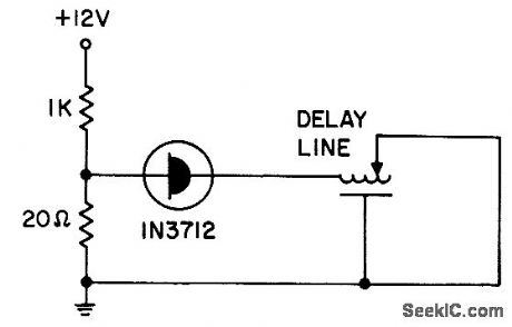
Tunnel-diode oscillator with General Radio 314-586 delay line produces square-wave output in range of 0.5 to 20 Mc.- Transistor Manual, Seventh Edition, General Electric Co., 1964, p 352. (View)
View full Circuit Diagram | Comments | Reading(1360)
9_KC_INDUCTION_RECEIVER
Published:2009/7/19 23:18:00 Author:Jessie
Thermistor network in base circuits of transistors provide thermal compensation between -30 and +140°F, for picking up messages broadcast from roadside telephone-line loops.-E. A. Hanysz, J. E. Stevens, and A. Meduvsky, Communication System for Highway Traffic Control, Electronics, 33:42, p 81-83. (View)
View full Circuit Diagram | Comments | Reading(665)
Scope_calibrator
Published:2009/7/19 23:18:00 Author:Jessie

This circuit uses an LM3909 to produce a precision square-wave signal that is used to calibrate scopes and scope probes or to check the gain and transient response of audio amplifiers (as described in chapter 1). The output is adjustable (with the 1-kΩ pot) and can be held to within a few tenths percent of 1 V.The output signal is a clean rectangular wave of about 1.5 ms On and 5.5 ms Off.The 0.01% temperature coefficient of the LM113 regulator results in negligible drift of the waveform amplitude under lab conditions. Because the circuit is battery powered, there is no inconvenient line cord, and no noise or hum. National Semiconductor. Linear Applications Handbook 1991 p 404 (View)
View full Circuit Diagram | Comments | Reading(0)
PREFERRED_2000_83000_PPS_BLOCKING_OSCILLATOR
Published:2009/7/19 23:18:00 Author:Jessie

Parallel-triggered circuit responds to trigger pulses separated by only few microsec, as required for distance-mark generators and pulse coding circuits. Input is positive, with minimum of 15 V, and output is positive. R6 is 220 ohms. R7 is maximum that will just suppress ringing.-NBS, Handbook Preferred Circuits Navy Aeronautical Electronic Equipment, Vol. I, Electron Tube Circuits, 1963, PC 47, p 47-2. (View)
View full Circuit Diagram | Comments | Reading(654)
OVERVOLTAGE_CROWBAR
Published:2009/7/19 23:17:00 Author:Jessie

Components within dashed lines protect regulator IC from over current condition frequently encountered when zener-SCR crowbar is used across output.Regulated output is 5 V with IC shown. Article gives operating details of circuit and equation for shutdown time, which is about 1 s.-S. J. Pirkle, Circuit Protects Power Supply Regulator from Overcurrent, EDN Magazine, Feb. 5, 1973, p89. (View)
View full Circuit Diagram | Comments | Reading(733)
Triac_trigger
Published:2009/7/19 23:16:00 Author:Jessie

This circuit uses an LM3909 (operating from a standard 5-V logic supply) to trigger a triac (chapter 8). With no gate input, or a TTL-logic high input, the LM3909 is biased off because pin 1 is tied to V+. With a logic low at the gate input', the LM3909 provides 10-μs pulses at about a 7-kHz rate. A TTL gate loaded only by this circuit is assumed because worst-case voltage swing might be insufficient. The trigger is not of the synchronized zero-crossing type (chapter 8) because the first trigger pulse after gating on could occur at any time. However, the repetition rate is such that after the first cycle, a triac is triggered within 8 V of zero (with a resistive load and a 1 15-Vac line). National Semiconductor Linear Applications Handbook 1991 p. 403 (View)
View full Circuit Diagram | Comments | Reading(0)
200_400_Mc_VARICAP_TUNED_OSCILLATOR_
Published:2009/7/19 23:15:00 Author:Jessie

Tuning range is achieved by adjusting Voricap bias voltage from 0.4 to 60 V.-E. Gottlieb and J. Giorgis, Tunnel Diodes-Using Them as Sinusoidal Generators, Electronics, 36:24, p 36-42. (View)
View full Circuit Diagram | Comments | Reading(622)
SLOT_ANTENNAFIER
Published:2009/7/19 23:15:00 Author:Jessie

T-bar-fed 420-Mc slot antennafier for space vehicles has gain of 10 db, 100-Mc bandwidth, and 7.8 db noise figure.-J. F. Rippin, Making the Antenna on Active Partner, Electronics, 38:16, p 93-96. (View)
View full Circuit Diagram | Comments | Reading(546)
Series_shunt_chopper_for_low_input_voltages
Published:2009/7/19 23:10:00 Author:Jessie

Series-shunt chopper for low input voltages (courtesy Motorola Semiconductor Products Inc.). (View)
View full Circuit Diagram | Comments | Reading(613)
SSB_PRODUCT_DETECTOR
Published:2009/7/19 23:27:00 Author:Jessie
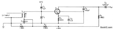
Square-law relationship between transconductance and drain current makes mos fet ideal for product detector in ssb receivers.-G. G. Luettgenau and S.H. Branes, Designing With Low-Noise MOS FETs: A Little Different But No Harder, Electronics, 37:31, p 53-58. (View)
View full Circuit Diagram | Comments | Reading(1027)
ELECTRIC_TUNING_FOR_600_to_1200_MC
Published:2009/7/19 23:27:00 Author:Jessie

Lumped-constant technique is used with voltage-tunable ferroelectric capacitors to provide 10 mw into 50 ohms.-T. W. Buller, Jr., Ferroelectrics Tune Electronic circuits, Electronics, 32;3, p 52-55. (View)
View full Circuit Diagram | Comments | Reading(601)
| Pages:840/2234 At 20821822823824825826827828829830831832833834835836837838839840Under 20 |
Circuit Categories
power supply circuit
Amplifier Circuit
Basic Circuit
LED and Light Circuit
Sensor Circuit
Signal Processing
Electrical Equipment Circuit
Control Circuit
Remote Control Circuit
A/D-D/A Converter Circuit
Audio Circuit
Measuring and Test Circuit
Communication Circuit
Computer-Related Circuit
555 Circuit
Automotive Circuit
Repairing Circuit